
Fireblocking device

a technology of fireblocking device and spherical block, which is applied in boring tools, roof covering ventilation, building components, etc., can solve the problems of difficult to stop fire spreading, considered it possible to combine the demand for venting and fire resistance, and considered too unsafe for activated dampers

Active Publication Date: 2009-06-02
SCUTI
View PDF27 Cites 88 Cited by
  • Summary
  • Abstract
  • Description
  • Claims
  • Application Information

AI Technical Summary

Benefits of technology

The device effectively prevents fire spreading by heat conduction, radiation, and convection, maintaining airflow while keeping combustible materials safe, and is non-combustible, easy to install, and maintenance-free, with no mechanical parts to ignite.

Problems solved by technology

Such areas are not easy accessible, and fires that take hold here, often result in dramatic consequences.
Such fire spreading is hard to stop, and thus far one has not considered it possible to combine the demand for venting and fire resistance.
Activateable dampers are considered to be too unsafe because flames can pass for minutes before closing, because of the weathering, because of mechanical and movable parts and because of dry materials, which can ignite before closing.
Known patents and solutions for preventing fire spreading in openings for air passages have a weakness in that, during a period before they are activated, they allow flames to pass through and ignite combustible gas or easily ignitable solid materials on the side that shall be protected.
Some of them also leave cracks, which make flame tongues and smoke spreading possible, even when they are closed.

Method used


Image

  • Fireblocking device
  • Fireblocking device

Examples


Embodiment Construction

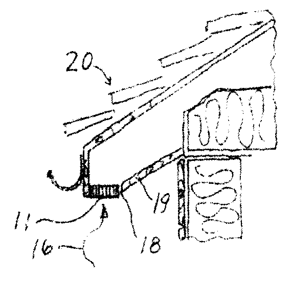
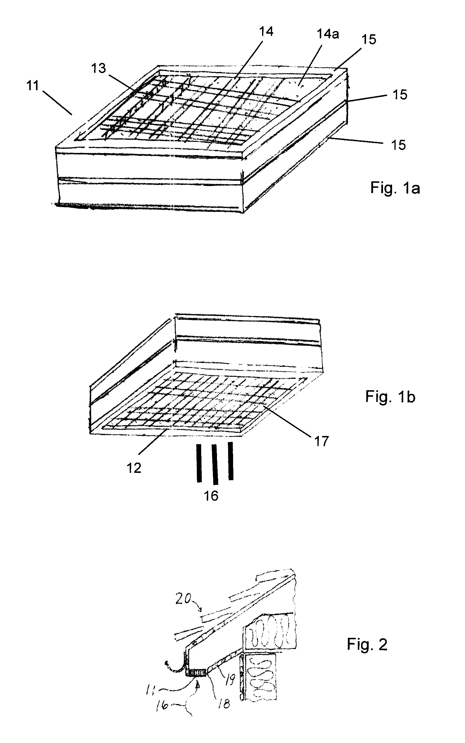
[0025]FIGS. 1a and 1b show a fireblocking device 11 according to the invention, which is made up of a lower, rectangular plate 12 of a grille that is treated with an intumescent material, disposed on the inlet side of the ventilating device, and an upper corresponding rectangular plate 13 of a heat absorbing and heat storing material in the form of perforated metal or metal pipes 14 filled with liquids, minerals or mixtures thereof, through which plate 13 air can flow, and which is disposed on the outlet side of the ventilating device. Over this, there is placed a rim frame 15 of a heat-insulating material, which can interrupt a heat bridge. Such a heat-insulating frame 15 can alternatively or additionally be placed between the two plates 12 and 13.

[0026]This embodiment requires an upwardly directed flame in the direction 16 from below, as will be apparent from the following.

[0027]The two elements can have an arbitrary shape, depending on the field of application. They can also be m...


PUM


Abstract

Fireblocking device for preventing transfer of fire through ventilating apertures or similar passages, in openings for thermal fire ventilation, in ventilation ducts, in process plants or in vented facade exteriors, in vented fire blankets, vented fire protective curtains or vented protective screens against explosions. The device includes a combination of a heat absorbing and heat storing body, and an element which includes and / or adsorbs and intumescent material.

Description

[0001]This application is a filing under 35 USC 371 of PCT / NO2003 / 000238 filed Jul. 4, 2003.BACKGROUND OF THE INVENTION[0002]1. Field of the Invention[0003]The invention relates to a fire blocking device as indicated in claim 1, in particular for blocking flames, which can be transferred through ventilation grates and similar apertures with air transfer. With “fireblocking device” is here ment a passive element, open for air transfer, which prevents the spreading of fire by penetration of flames, heat conduction, convection or radiation.[0004]2. Description of Related Art[0005]Open flame arresters are known, which function as heat sink for explosive combustion or short-lived fireballs. They are arranged open, so that air transfers, but not flames. They are often made of steel, either as perforated plates or mesh or as steel strip bodies pressed together, and similar. The function of arresting deflagration combustion first became known as Davy's net in 1815, used by Sir Humphrey Davy...

Claims


Application Information

Patent Timeline
Patent Type & Authority Patents(United States)
IPC IPC(8): E04C2/42A62C2/06E04B1/62E04B1/94E04D13/17
CPCA62C2/065E04B1/947E04D13/178
Inventor JENSEN, GEIR
Owner SCUTI
Learn More