Seat belt anchor device and method

a seat belt and anchoring device technology, applied in the direction of safety belts, furniture parts, pedestrian/occupant safety arrangements, etc., can solve the problems of increasing assembly time and cost accordingly, difficult for the installer to know when the anchoring head has been properly aligned, and difficult to give a clear view of the anchoring stud

Inactive Publication Date: 2009-06-02
TAKATA SEAT BELTS
View PDF23 Cites 21 Cited by
  • Summary
  • Abstract
  • Description
  • Claims
  • Application Information

AI Technical Summary

Benefits of technology

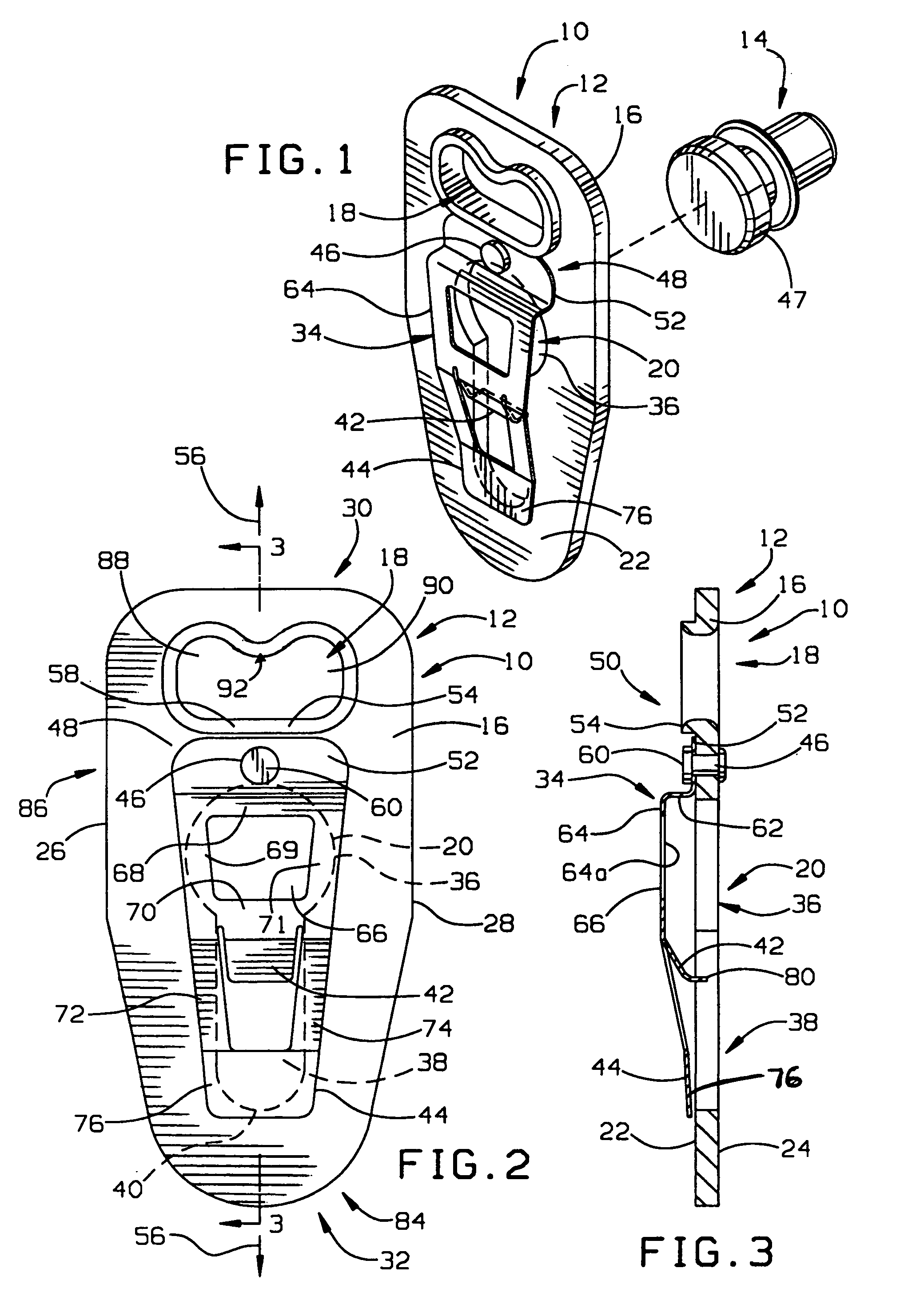
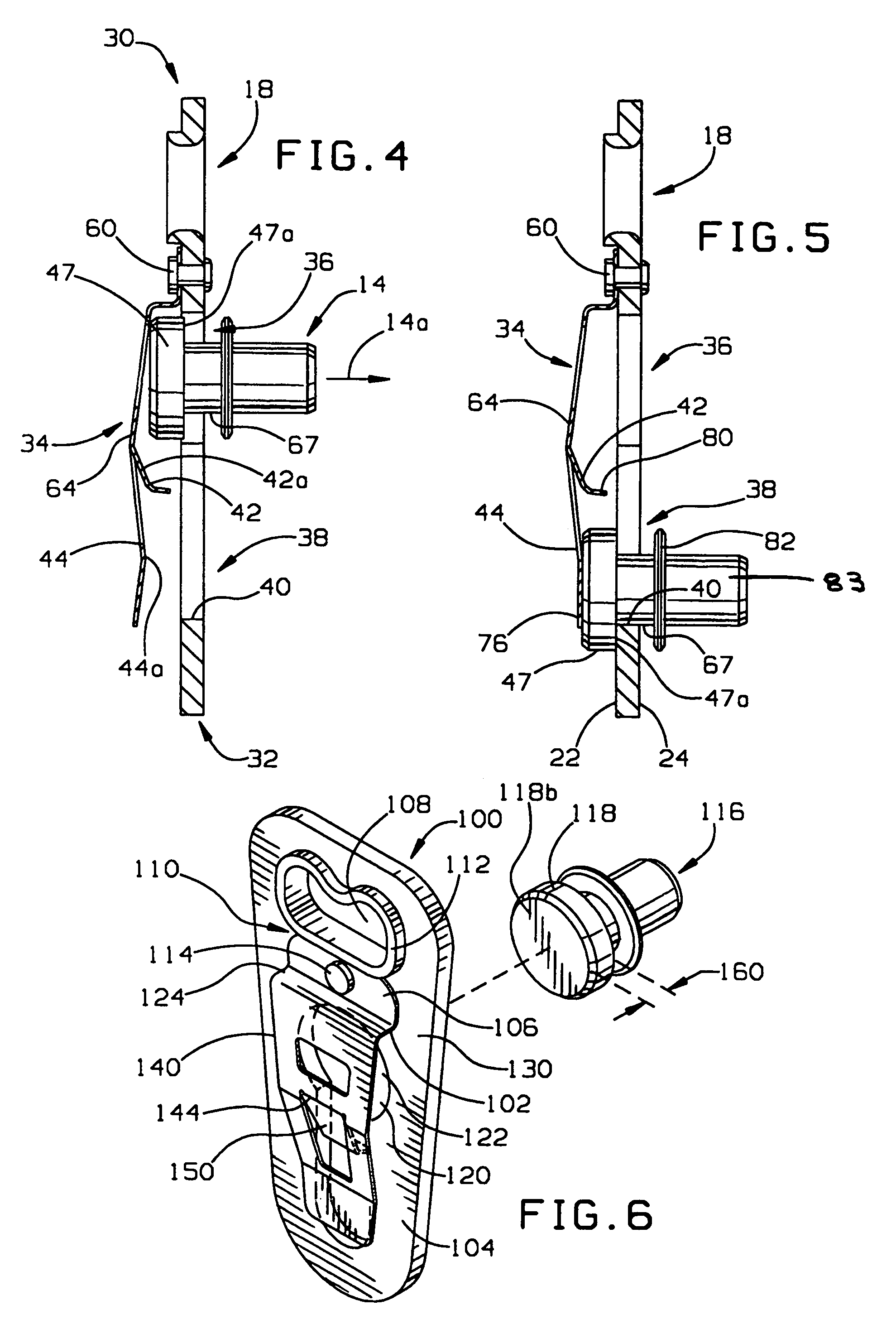
[0007]In accordance with the invention, a seat belt anchor device and method of installing a seat belt anchor device are provided. The seat belt anchor device includes a plate member formed with a keyhole opening which receives a stud with the plate member then being shifted to an installed position relative to the stud. A spring retainer is connected at an end portion thereof to the plate member and extends in overlying relation to the keyhole opening serving to maintain the plate body and stud in the installed position. Stop structure is provided that limits pivoting of the retainer to maintain it in its overlying relation to the keyhole opening. One advantage provided by the stop structure is that it allows a single fastener, e.g. rivet, to be utilized to secure the end portion of the spring retainer to the plate body which keeps assembly time to a minimum by avoiding a second riveting operation for securing the spring retainer to the plate member. Further, the stop structure can be formed integrally with the plate member body so that the number of parts and costs associated therewith for the anchor device are also kept to a minimum.
[0010]In another aspect, a method for installing a seat belt anchor to a stud is provided. The method includes providing a plate body having a spring retainer which extends over a keyhole opening of the plate body and is secured to the plate body at a single location, and restricting pivoting of the spring retainer during installation by a raised stop of the plate body.
[0017]The offset body portions of the plate member are advantageous during installation. By having the connected upper end portion of the spring retainer flush on the upper body portion of the plate member, the spring retainer presents less of an obstacle or potential catch site for the anchor device during installation. As mentioned, the spring retainer arm serves as an indicator for providing the installer with tactile feedback as to the axial position of the plate member and stud head relative to each other.
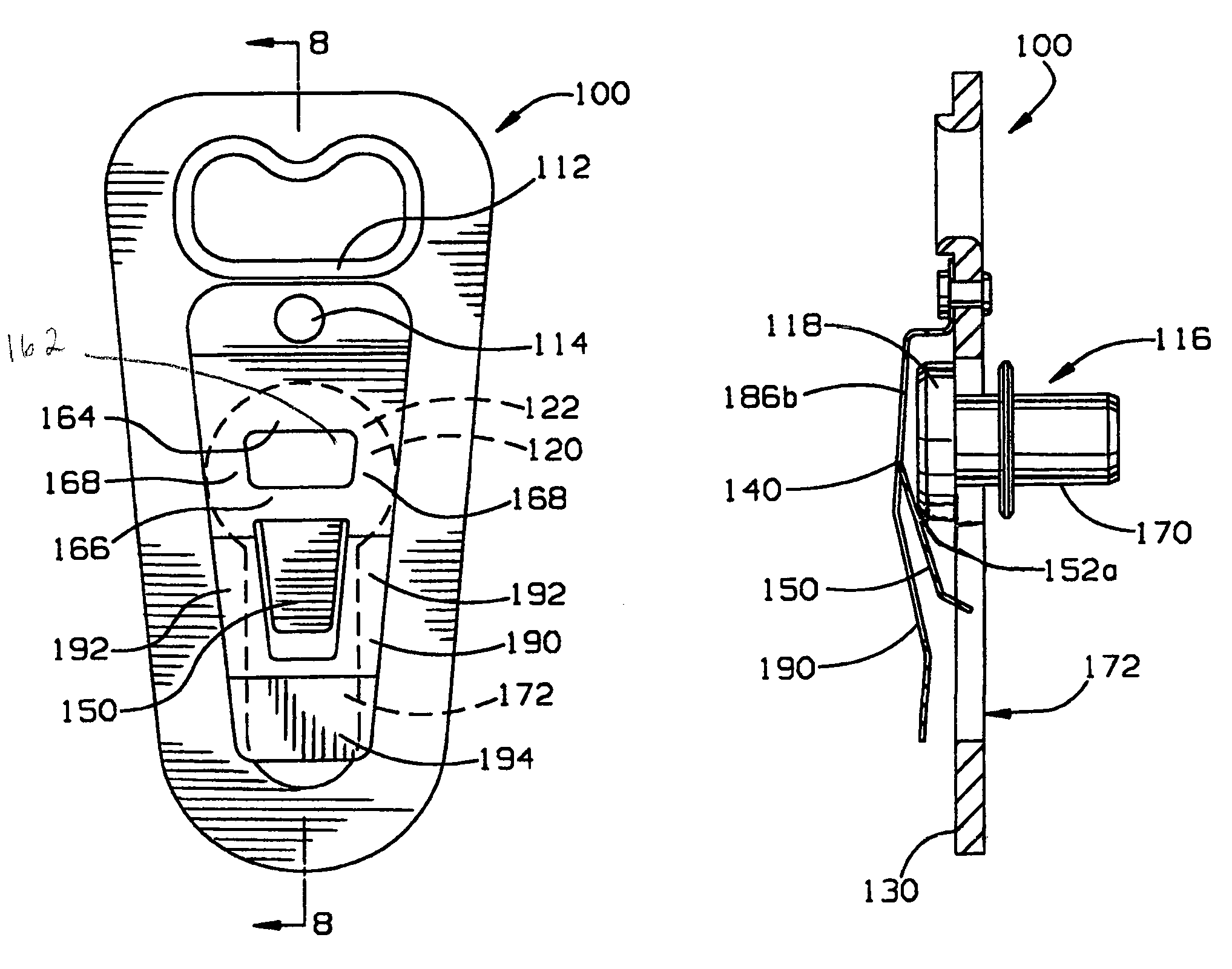
[0018]In a further form similar to the offset plate body form described above, the spring retainer may have an arm portion that extends toward the plate body for cooperating with the underside of the stud head. The arm portion is cammed outwardly away from the plate body as the anchor device is shifted relative to the stud head to install the device on the stud. Once the plate member, and specifically the arm portion thereof, has been shifted sufficiently relative to the stud head so as to be clear thereof, the arm resiliently returns to an interference position to the side of the stud head along the slot portion of the keyhole opening. When in the interference position, an upturned prong or prongs at the end of the arm portion are positioned adjacent or against a bottom or underside surface of the stud head to restrict relative motion between the stud and the anchor device during certain impacts with the vehicle.
[0019]More particularly, the end prong or prongs cooperate with a distal arm portion of the spring retainer to exert a generally axially directed force in opposing directions on the stud at the head thereof. In this manner, impacts aligned with the stud axis, such as side impacts, are less likely to cause separation between the stud head and spring retainer that may otherwise be sufficient to allow the plate to shift longitudinally relative to the stud head potentially compromising retention of the anchor device on the stud.
[0021]In this form, the spring retainer is preferably arranged so that it only overlies the narrow slot portion of the keyhole opening. Rather than using an end of a retainer arm portion, the spring retainer has an opening that is fit over the stud head when the plate member is shifted longitudinally during installation. The spring retainer is configured so that it snaps onto the stud head with the trailing portion of the edge of the opening in position adjacent the stud head to keep the stud from backing out from the end of the narrow slot portion of the keyhole opening in the installed position of the anchor device on the stud.

Problems solved by technology

In some instances, seat belt systems may be installed after the vehicle seats are finished or partially finished, so that it is difficult to give a clear view of the anchor stud.
One problem lies in the manner in which the spring retainer is secured to the plate member.
In addition to increasing part costs, there are two separate riveting operations that need be performed to attach the spring retainer to the plate member thus increasing assembly time and cost accordingly.
In addition, during the fitting of the stud head through the keyhole opening, it can be difficult for the installer to be able to know when the stud head has been properly aligned with the keyhole opening for this procedure.
Without repositioning the plate so that the stud head is closer thereto, upward pulling on the plate will generate large forces resisting this movement by the spring retainer and the retainer arms thereof making installation more difficult than is desired.
Other problems include space constraints that may be present during installation that can make it difficult to properly align the plate member and stud for fitting the stud head through the key hole opening.

Method used


Image

  • Seat belt anchor device and method
  • Seat belt anchor device and method
  • Seat belt anchor device and method

Examples


Embodiment Construction

[0032]In FIGS. 1-5, a seat belt anchor device 10 is shown. The seat belt anchor device 10 includes a plate member 12 utilized to anchor a seat belt (not shown) to a stud 14 that can be in turn fixed to a lower portion of a seat frame, for example. The plate member 12 has a plate body 16 that can include an upper opening 18 for receiving seat belt webbing extending therethrough, and a opening 20 therebelow for receipt of the stud 14, as described hereinafter.

[0033]The plate body 16 has a relatively thin thickness between opposite surfaces 22 and 24, e.g. approximately 3.2 millimeters (see FIG. 3). The plate body 16 also has an elongate construction with sides 26 and 28 that are spaced from each other transversely across the plate body surfaces 22 and 24 by a much smaller amount than they extend along the length of the plate body 16 from proximate end 30 to distal end 32 thereof (FIG. 2). In this regard, the plate member 12 is provided with a long, narrow and thin construction which i...


PUM


Abstract

A seat belt anchor device and method are provided for anchoring a seat belt to a stud. The device includes a plate member having a keyhole opening into which the stud is fit with the plate member pulled upwardly to bring the stud to the installed position relative to the plate member. A spring retainer member keeps the stud and plate member in their installed position. A stop is provided to limit pivoting of the spring retainer member relative to the plate member. In some forms, the spring retainer includes resilient clamping portions for clamping engagement with the stud head therebetween in the installed portion.

Description

FIELD OF THE INVENTION[0001]The invention is to a seat belt anchor device and method and, more particularly to seat belt anchor device of the type utilizing a keyhole opening for anchoring a seat belt to a stud.BACKGROUND OF THE INVENTION[0002]In seat belt systems for vehicles, it is often desirable to be able to anchor the seat belt at one of its anchor points to a stud that is fixed to the seat frame near the floor of the vehicle. In some instances, seat belt systems may be installed after the vehicle seats are finished or partially finished, so that it is difficult to give a clear view of the anchor stud. For example, the anchor may have to be fit through an opening or gap between the plastic trim of the seat and the seat frame member to which the stud is affixed. It may also be the case that the anchor has to be fit between a small opening formed in the upholstery for being lowered down to the lower stud via a fishing installation tool and then connected to the stud.[0003]One su...

Claims


Application Information

Patent Timeline
Patent Type & Authority Patents(United States)
IPC IPC(8): B60R22/00B60R22/18
CPCB60R22/24
Inventor HALL, CHRISTOPHER D.
Owner TAKATA SEAT BELTS
Why Eureka
Try Eureka