Plug-in amp/watt power meter

a power meter and plug-in technology, applied in the direction of coupling device connection, instruments, transportation and packaging, etc., can solve the problems of determining the electrical load, i.e., current draw, time-consuming to electrically isolate the appropriate electrical device, etc., to achieve cost savings, light weight, and high portability

Active Publication Date: 2009-06-02
RELIANCE CONTROLS
View PDF12 Cites 43 Cited by
  • Summary
  • Abstract
  • Description
  • Claims
  • Application Information

AI Technical Summary

Benefits of technology

[0009]The present invention is directed to a power meter having a measuring circuit composed entirely of analog components that measures the instantaneous current draw of one or more electrical devices, such as home appliances. The power meter may be in the form of a hand-held device, which includes elongated connections that allow a homeowner to measure and monitor a value of the current draw of an electrical dev

Problems solved by technology

However, determining the electrical load, i.e., current draw, of selected electrical loads is more difficult.
A drawback of such an approach is that all loads not to be measured, of which there may be dozens for a single home, must be electrically isolated.
Regardless of which approach is taken, it can be time-consuming to electrically isolate the appropriate electrical devices.
Moreover, if the homeowner wanted to measure the energy usage over time, the electrical isolation would be required throughout the measurement interval, which may be undesirable and impractical.
These devices typically include rather complex digital circuits that measure various ele

Method used


Image

  • Plug-in amp/watt power meter
  • Plug-in amp/watt power meter
  • Plug-in amp/watt power meter

Examples


first embodiment

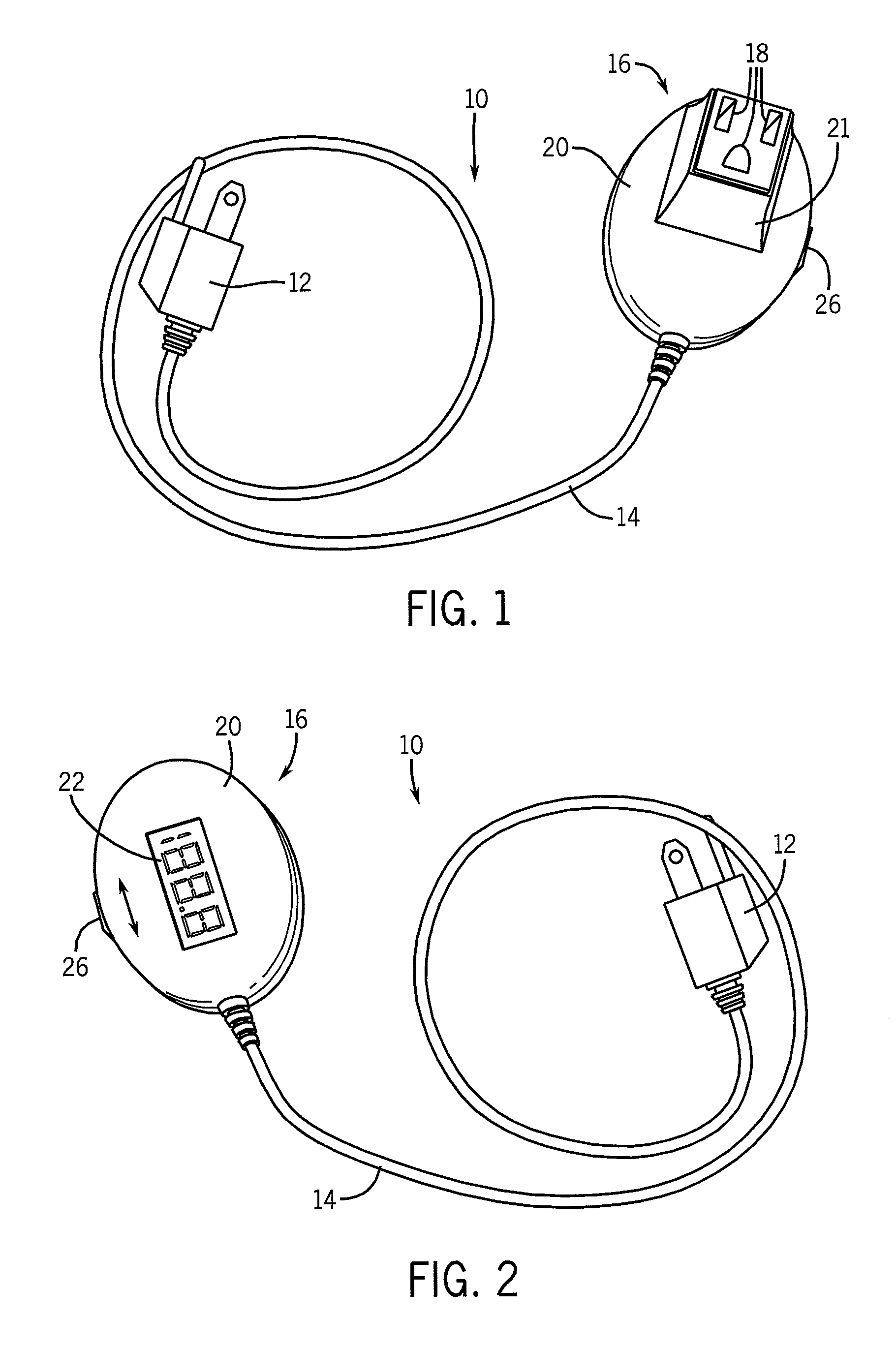
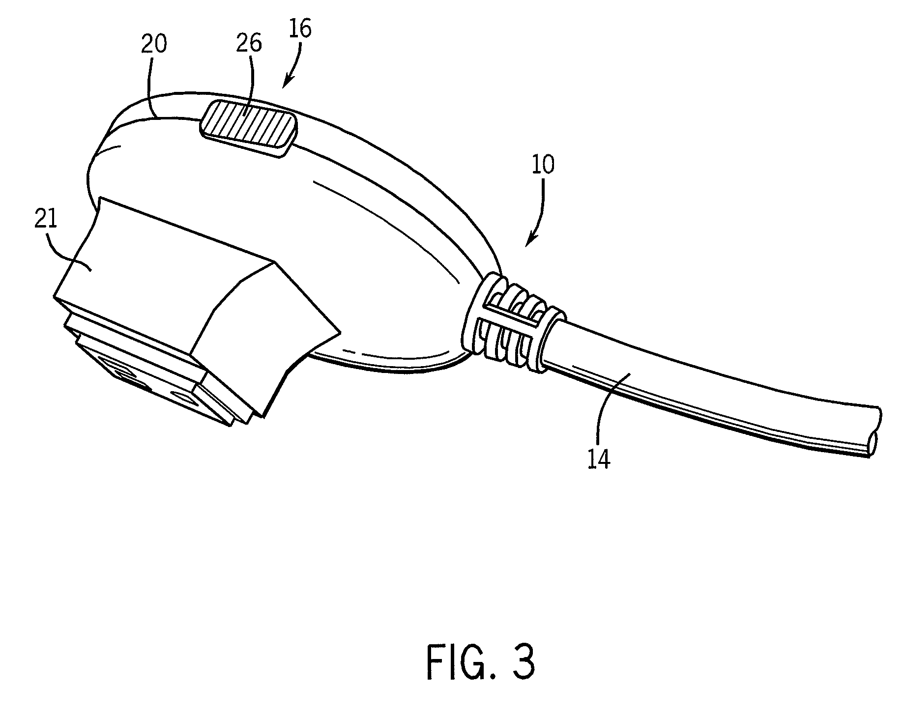
[0022]With regard now to the drawing figures in which like reference numerals designate like parts throughout the disclosure, a plug-in power meter constructed according to the present invention is indicated generally at 10 in FIG. 1. The power meter 10 includes a plug 12 disposed at one end that may be engaged with a conventional electrical outlet (not shown), and a cord 14 extending outwardly from the plug 12. The cord 14 contains conductive wires (not shown) that enable electrical power to be supplied from the outlet to which the plug 12 is connected, through the cord 14 to a receptacle 16 attached to the cord 14 opposite the plug 12. The receptacle 16 includes a number of openings 18 in a configuration similar to that of a conventional outlet, such that a plug (not shown) connected to a suitable electric device or appliance (not shown), such as a furnace, air conditioner, sump pump, microwave oven, refrigerator, freezer, toaster, coffee maker, computer, radio, and the like, can ...

second embodiment

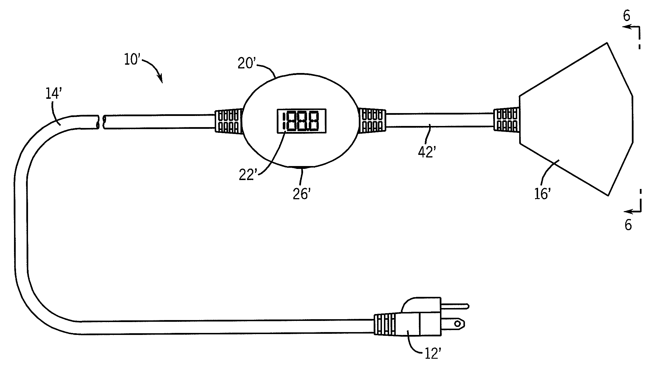
[0028]In a second embodiment on the present invention as shown in FIGS. 5-6, in which like components are designated with primed reference characters, the power meter 10′ includes the plug 12′, the cord 14′, and the housing 20′ with the display 22′ and the switch 26′ as in the previous embodiment. The cord 14′ is preferably formed to have a length similar to that for a normal extension cord. However, the power meter 10′ also includes a second cord 42′ that extends away from the housing 20′ opposite the cord 12′ to a receptacle 16′. It is understood that either of the cords 14′ or 42′ may have any desired length. The receptacle 16′ includes multiple sets of openings 18′ in the configuration of a conventional electrical outlet, such that multiple plugs from multiple electric devices or appliances can be simultaneously connected to the receptacle 16′ for determining a combined amperage or wattage for all of the appliances when in operation. Additionally, the receptacle 16′ can include ...


PUM


Abstract

A power meter has a measuring circuit composed entirely of analog components that measures the instantaneous current draw of one or more electrical devices, such as home appliances. The power meter may be in the form of a hand-held device that includes elongated connections that allow a homeowner to measure the current draw of an electrical device without significant displacement of the electrical device. In addition to measuring current draw, the power meter may provide an estimated wattage consumed by the measured electrical devices.

Description

CROSS REFERENCE TO RELATED APPLICATION[0001]The present application claims the benefit of U.S. Ser. No. 60 / 823,588, filed Aug. 25, 2006, the disclosure of which incorporated herein by reference.BACKGROUND OF THE INVENTION[0002]The present invention relates to power meters and, more particularly, to a power meter to which the collective current draw of multiple loads is measured using a measuring circuit composed entirely of analog components.[0003]Whether it be as a matter of general interest or to determine the size needed for an auxiliary power supply, such as an electric generator, homeowners are increasingly interested in the energy use associated with the electric load of the home and, more particularly, of selected electrical loads. The total electrical load of a home may be determined through monitoring the utility power meter typically located exteriorly of the home. However, determining the electrical load, i.e., current draw, of selected electrical loads is more difficult....

Claims


Application Information

Patent Timeline
IPC IPC(8): H01R33/945
CPCG01R1/0408H01R25/003G01R15/12G01R21/00H01R13/6683H01R13/6691H01R31/065
Inventor CZARNECKI, NEIL A.
Owner RELIANCE CONTROLS
Why Eureka
Try Eureka