Device for ionizing particles carried in an airflow, for ventilation, heating, and/or air-conditioning system in particular

a technology for airflow and ionizing particles, which is applied in the direction of electrostatic separation, electrode carrying means, and electrostatic construction, etc., can solve the problems of difficulty in obtaining these devices at a competitive price, and achieve the effect of simplifying operations and facilitating industrial production

Inactive Publication Date: 2009-06-02
VALEO SYST THERMIQUES
View PDF25 Cites 6 Cited by
  • Summary
  • Abstract
  • Description
  • Claims
  • Application Information

AI Technical Summary

Benefits of technology

[0006]The purpose of this invention is to propose a device for ionizing particles carried in an airflow, which is designed to be placed therein, upstream from a device for collecting these particles, in particular by means of electrostatic precipitation or the like. More particularly, it is sought to propose such a device, which is compact and structurally simple, in order to facilitate its industrial production and simplify the operations for assembling the elements of which it is made.
[0013]In particular, the chassis is made in the form of a frame receiving the support at one of its large surfaces, and the unitary piece at its other large surface. In the case where the supports constitute a unitary piece from one end to the other of the loop ends, the wires are capable of being installed on this unitary piece prior to being put in place on the chassis. From these arrangements, it follows that the assembly of the first electrodes and the second electrodes on the chassis is simple and fast, based on their installation on either side of the chassis, by means of an intermediate element onto which the first electrodes and second electrodes are respectively assembled, this intermediate element being formed by the cross-pieces, in the case of the first electrodes, and by the supports, in the case of the second electrodes.

Problems solved by technology

This results in a difficulty in obtaining these devices at a competitive price, along with a compact design and a limited number of elements.

Method used


Image

  • Device for ionizing particles carried in an airflow, for ventilation, heating, and/or air-conditioning system in particular
  • Device for ionizing particles carried in an airflow, for ventilation, heating, and/or air-conditioning system in particular
  • Device for ionizing particles carried in an airflow, for ventilation, heating, and/or air-conditioning system in particular

Examples


Embodiment Construction

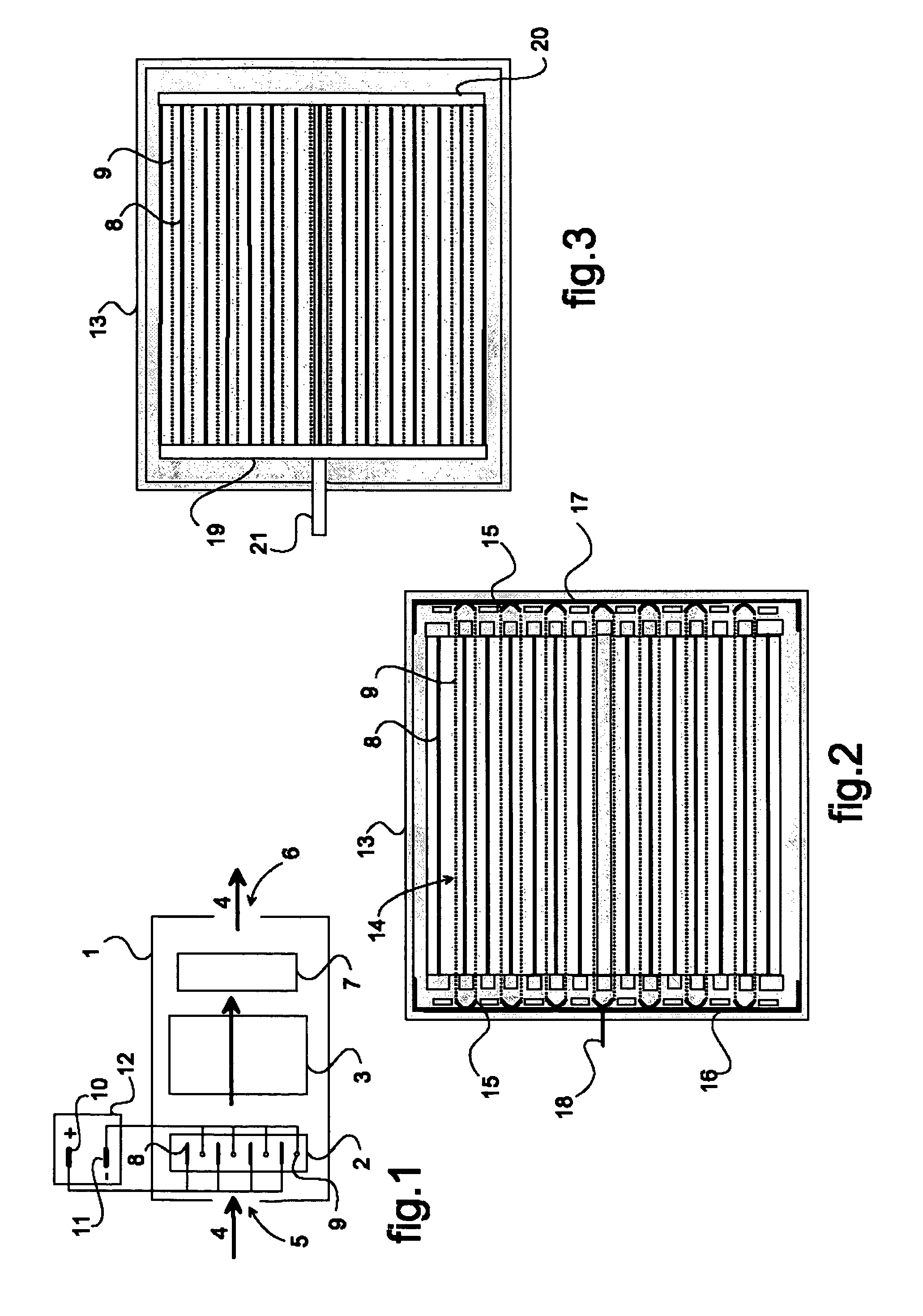
[0026]In FIG. 1, a housing 1 contains an electrostatic apparatus 2, 3 designed to purify an airflow 4 circulating therethrough, by retaining the particles carried in the airflow 4, such as particles of dust, smoke or the like. This apparatus 2, 3 includes an ionizing device 2 designed to electrically charge the particles and a device for collecting 3 the previously charged particles, e.g., by means of electrostatic precipitation. The housing 1 comprises an air inlet 5 and an air outlet 6, and contains a pulser 7 for circulating the airflow 4 through the electrostatic apparatus 2, 3. The housing 1 is likely to be that of a ventilation, heating and / or air conditioning system of a motor vehicle in particular. In this case, the pulser 7 is either that belonging to the system or an additional pulser. In this case again, the electrostatic apparatus 2, 3 is preferably placed at the air inlet 3 of the system or inside the ventilation, heating and / or air conditioning system, either upstream ...


PUM


Abstract

The object of the invention is a device for ionizing (2) particles carried in an airflow (4) circulating inside a system, this device (2) including at least two electrodes (8, 9) held by a chassis (13) and connected, respectively, to the corresponding terminals (10, 11) of a polarized electrical power supply. Two adjacent first electrodes (8) are arranged on either side of a second electrode (9), which is formed from at least one conductor cable (14). The latter (14) is hooked onto fingers (15) that are designed as an elastic part for tensioning the conductor cable (14) and that are held by the chassis (13).

Description

TECHNICAL FIELD OF THE INVENTION[0001]This invention belongs to the field of apparatus for treating an airflow circulating through a system, in particular for removing particles from it that it is carrying. This system, for example, is a ventilation, heating and / or air conditioning system, in particular for a motor vehicle. More particularly, the object of this invention is a device for ionizing said particles, with a view to causing their electrostatic precipitation on a collecting device placed downstream from the ionizing device of the invention.PRIOR ART[0002]Electrostatic apparatus are known that are designed for retaining particles, such as particles of dust, smoke or the like, which are present in an airflow circulating inside a system. These apparatus, for example, are used to purify the air of a ventilation, heating and / or air conditioning system, in particular for a motor vehicle.[0003]Among these apparatus are also known those whose design separates into two separate unit...

Claims


Application Information

Patent Timeline
Patent Type & Authority Patents(United States)
IPC IPC(8): B03C3/41
CPCB03C3/41B03C3/86
Inventor LADRECH, FREDERICLOUP, DIDIER
Owner VALEO SYST THERMIQUES
Why Eureka
Try Eureka