

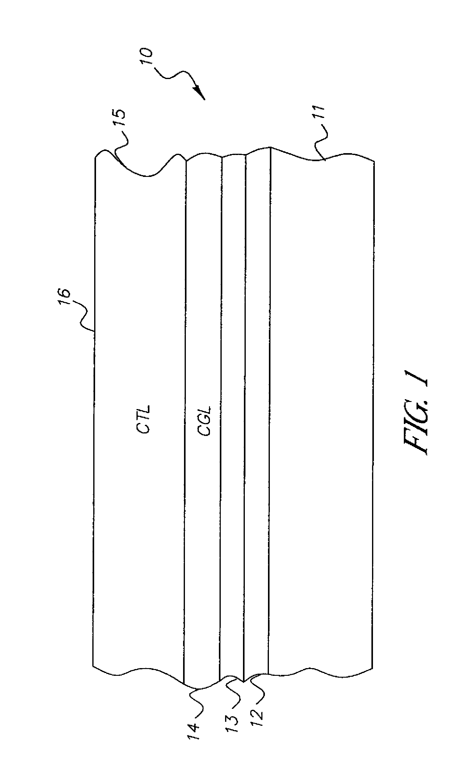
Condensation polymer photoconductive elements
a polymer and photoconductive element technology, applied in the field of electrotrophotography, can solve the problems of image defect, irregular quality of images produced with photoconductive elements, and affecting the quality of images produced with photoconductive elements, and achieve good resistance to injection, thick and uniform, and resist the effect of hole transpor
- Summary
- Abstract
- Description
- Claims
- Application Information
AI Technical Summary
Benefits of technology
Problems solved by technology
Method used
Image

Examples
example 1
[0117]The hydroxyl equivalent weight of polymer 4 (0.38 meq / mole of hydroxyl group) was calculated at 2632 grams. The NCO equivalent wt of the Trixene B7963 (including solvent) is reported at 681 grams by the manufacturer. This information was used to mix formulation 1 at a 1:1 polymer 6 to the Trixene B7963 diethyl malonate blocked isocyanate. A 40% excess hydroxyl was provided by the high molecular weight, hydroxyl-functional, partially hydrolyzed vinyl chloride / vinyl acetate resin UCAR (trademark) VAGH, obtained from Dow chemical. The materials were dissolved in 1,1,2 trichloroethane at a dilution appropriate for dip coating the appropriate thickness for the experiment. Dibutyl tin dilaurate from Aldrich Chemicals was used as a catalyst at 0.40 wt %.
[0118]
Formulation 1NCONCOEquiv-HydroxylEquiv-HydroxylEquivalentalentEquivalentalentEquivalentRatioWtWtGrammolemoleOH / NCOPolymer 426322180.0830.99TrixeneB7963681570.0841.01VAGH951320.0340.40TOTAL1.39
[0119]Formulation 1 was dip coated o...
example 2
[0125]Formulation 2, using polymer 5 (hydroxyl equivalent wt, calculated at 3864) was coated on nickel sleeve, following the procedure of example 1. The coated sleeves were evaluated for sensitometry and image quality in a Nexpress 2100 Digital printer at three different environmental conditions. The toe voltages and the overall breakdown numbers are shown in Table 5.
[0126]
Formulation 2NCONCOEquiv-HydroxylEquiv-HydroxylEquivalentalentEquivalentalentEquivalentRatioWtWtGrammolemoleOH / NCOPolymer 538461980.0530.85TrixeneB7963681430.0631.18VAGH951340.0360.57TOTAL1.41
[0127]
TABLE 5ToeToeToeVoltage @Voltage @Voltage @Barrier75 F. / 30%75 F. / 30%78 F. / 81%Breakdowng / ft2RHRHRH#Ctg 90.037993772.4Ctg 100.0791114682.1
example 3
[0128]Formulation 3, using polymer 6 (1111 hydroxyl equivalent wt) exclusively, provided a 60% excess hydroxyl equivalent. Nickel sleeves were coated using the procedure of Example 1.
[0129]
Formulation 3NCONCOEquiv-HydroxylEquiv-HydroxylEquivalentalentEquivalentalentEquivalentRatioWtWtGrammolemoleOH / NCOpolymer 611111990.1791.61Trixene0.110B7963681750.62VAGH95100.0000.00TOTAL1.61
[0130]The sleeves were evaluated in a Nexpress 21000 digital printer @ 7fF / 30% RH. The toe voltages are shown in Table 6
[0131]
TABLE 6Barrier Layerg / ft2CGL g / ft2Residual Voltage @ 75 F. / 30% RHCtg 110.040.0289Ctg 120.050.02113Ctg 130.060.03115
PUM
| Property | Measurement | Unit |
|---|---|---|
| thickness | aaaaa | aaaaa |
| thickness | aaaaa | aaaaa |
| mass | aaaaa | aaaaa |
Abstract
Description
Claims
Application Information