Extending the dynamic range of the TGS through the use of a dual intensity transmission beam

a transmission beam and dual intensity technology, applied in the field of tomographic imaging, can solve the problems of high heterogeneity of radioactive waste contained in drums, unable to obtain accurate quantitative results using current tomography techniques, and unable to meet the requirements of the density range, so as to reduce the measurement time

Active Publication Date: 2009-06-02
CANBERRA IND INC
View PDF4 Cites 0 Cited by
  • Summary
  • Abstract
  • Description
  • Claims
  • Application Information

AI Technical Summary

Benefits of technology

[0016]The attenuated transmission scan is appropriate for weakly attenuating views, such as the sides of the container. The full intensity transmission beam provides the attenuation information during more severe, highly-attenuating views. By automatically performing both transmission scans, the operator does not have to choose the appropriate beam intensity for each drum, nor repeat the assay with different transmission source settings, thus reducing measurement time. During image reconstruction, the system software determines which transmission data to use at each view according to predetermined criteria.

Problems solved by technology

Radioactive waste contained in drums can be highly heterogeneous in matrix distribution and may also exhibit a non-uniform and unrelated distribution of radionuclides.
Under such circumstances, accurate quantitative results can be difficult or even impossible to obtain using current tomography techniques.
Still, these analyses cannot go much beyond a density waste matrix of approximately 1.5 g / cc.
However, if such a system were used to measure a drum with widely varying internal densities, the beam would likely be either too bright for areas with low density or too dim for areas with high density.
However, the beam will not penetrate the high density portions and will not produce useful data.
This will blind the detector in areas with low density and not provide useful data.
This type of imaging is impractical and inefficient due to the time required to conduct a thorough assay.
Also, the costs associated with purchase and maintenance of two transmission sources is significant.
Also, current systems can only handle low to moderate density waste matrices.
Automated production environments are often required to process drums with much higher densities and sizes, making accurate assays difficult if not impossible.

Method used


Image

  • Extending the dynamic range of the TGS through the use of a dual intensity transmission beam
  • Extending the dynamic range of the TGS through the use of a dual intensity transmission beam
  • Extending the dynamic range of the TGS through the use of a dual intensity transmission beam

Examples


Embodiment Construction

[0028]Obtaining a high quality attenuation map is a prerequisite to obtaining an accurate tomographic gamma scanner (TGS) assay. For highly attenuating items, counting precision is a limiting factor for some views. The dynamic range can be extended by using a strong, high-energy source in conjunction with a beam modulator allowing high and low transmission modes. For modest attenuation, the weak or low beam intensity is used to obtain transmission factors. When count rates are too low to be viable, the system automatically uses the high beam data. Ordinarily, the high beam would saturate the detector due to excessive dead-time and pile up; hence, the transmission data from the high beam cannot be used throughout the range.

Implementation

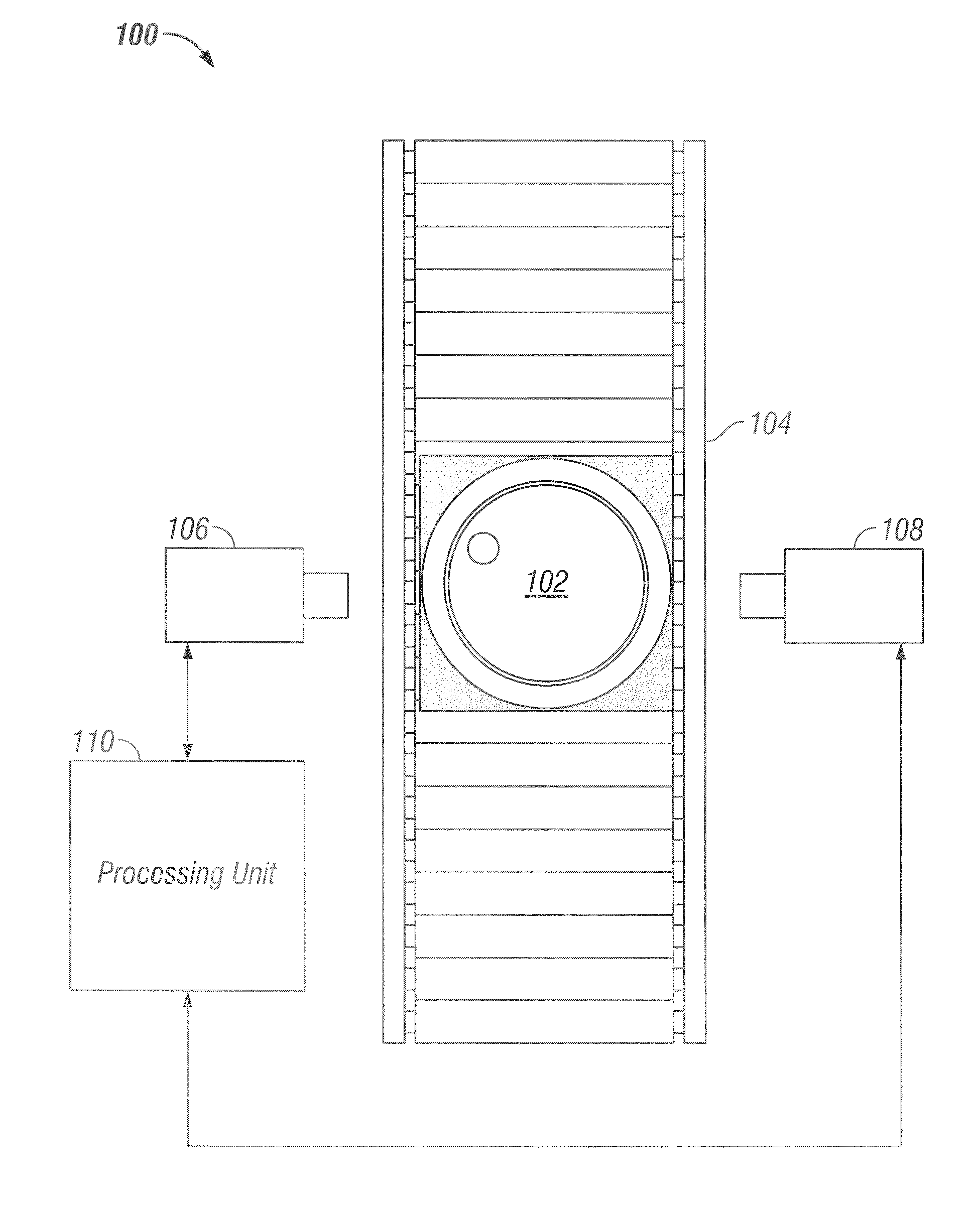
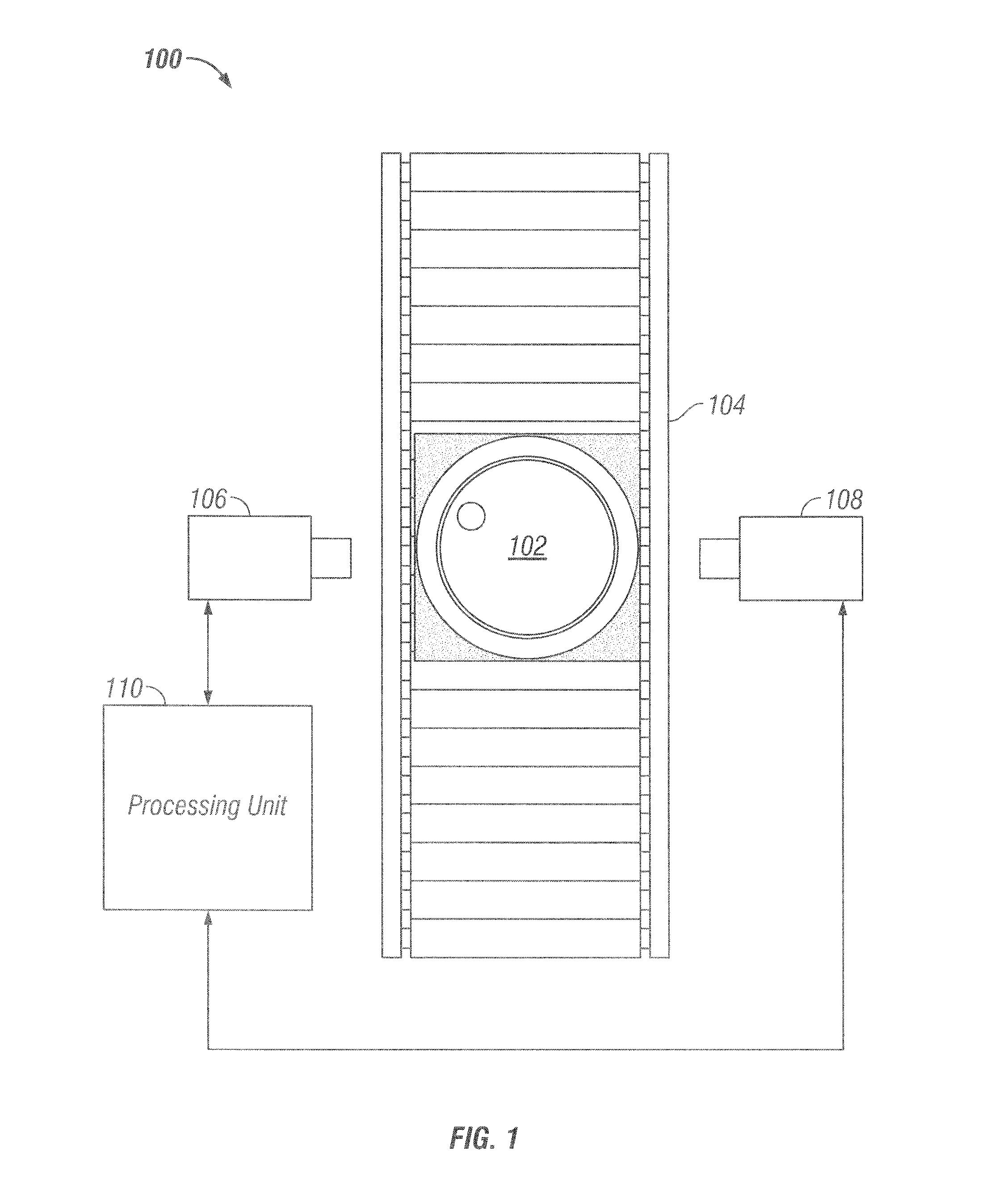
[0029]FIG. 1 depicts a basic block diagram 100 of the invention in its present embodiment. In a typical automated production environment, a drum containing a heterogeneous distribution of radioactive waste 102 passes before the tomographic gamma scann...


PUM


Abstract

A method for automating and extending the density range for gamma ray attenuation correction algorithms for all classes of non-destructive assay systems including those without automated shutters or automated collimators. A system and software for implementing the method are also provided. The system features a dual-intensity transmission source and utilizes a three pass scanning protocol. The high-energy source in conjunction with a beam modulator produces a high and low energy beam. Automated software determines which beam data to use in tomographic reconstruction of an object being scanned.

Description

CROSS-REFERENCE TO RELATED APPLICATIONS[0001]This application claims the benefit of provisional Application No. 60 / 830,527, filed Jul. 13, 2006.STATEMENT REGARDING FEDERALLY SPONSORED RESEARCH OR DEVELOPMENT[0002]Not ApplicableTHE NAMES OF THE PARTIES TO A JOINT RESEARCH AGREEMENT[0003]Not ApplicableINCORPORATION-BY-REFERENCE OF MATERIAL SUBMITTED ON A COMPACT DISC[0004]Not ApplicableBACKGROUND OF THE INVENTION[0005]1. Field of the Invention[0006]The present invention relates to tomographic imaging. More specifically, the present invention relates to a system and method for extending the density range for tomographic imaging of potentially radioactive attenuating objects in an industrial environment.[0007]2. Description of Related Art including information disclosed under 37 CFR 1.97 and 1.98[0008]Radioactive waste contained in drums can be highly heterogeneous in matrix distribution and may also exhibit a non-uniform and unrelated distribution of radionuclides. Under such circumsta...

Claims


Application Information

Patent Timeline
Patent Type & Authority Patents(United States)
IPC IPC(8): G01T1/164
CPCG01N23/06G01T1/167G01N2223/1013G01N2223/424G01N2223/626
Inventor CROFT, STEPHENKANE, SUSAN C.MCCLAY, PATTYMCELROY, JR., ROBERT D.MUELLER, WILHELM F.VILLANI, MARCEL F.
Owner CANBERRA IND INC
Why Eureka
Try Eureka