Agricultural machine for cutting products

a technology for cutting products and agricultural machines, applied in the field of agricultural machines, can solve the problems of increasing the width of strips, the driver of the carrier vehicle cannot readily and constantly see all the working units, and the arrangement of the lateral working units is a major drawback

Inactive Publication Date: 2009-06-09
KUHN SA
View PDF43 Cites 11 Cited by
  • Summary
  • Abstract
  • Description
  • Claims
  • Application Information

AI Technical Summary

Benefits of technology

[0013]It is therefore an objective of the invention to solve these main difficulties by guaranteeing the driver good visibility under all conditions of work and of transport, and to do so in complete safety regardless of the working conditions.
[0015]Arranging the lateral working units around the carrier vehicle and the configuration whereby these are folded around the carrier vehicle, according to the invention, lead to an agricultural machine that has a good efficiency but also a reduced transport width.
[0016]Furthermore, positioning said lateral working units substantially level with the front wheels and on the sides of the carrier vehicle and moving the driver's cab forward when the lateral working units are in this forward position, allow a good visibility to all the working units.
[0017]Furthermore, in this configuration according to the invention, the instantaneous center of rotation, in bends or about-turns, lies substantially on a line passing through the lateral working units, which makes it possible to maintain a good overlap between the frontal working units and the lateral working units in order to prevent uncut strips of land remaining between them.
[0018]The use of an agricultural machine with multiple working units according to the invention offers a combination that allows a high output.

Problems solved by technology

This configuration of the lateral working units has the drawback that the driver of the carrier vehicle cannot readily and constantly see all the working units and anticipate unevennesses of the ground or obstacles by raising said working units, when turning to avoid said obstacles or alternatively when adapting the speed of said vehicle.
Said arrangement of the lateral working units also presents a major drawback when driving the agricultural machine around bends.
In fact, in this configuration of use, the working units no longer offer a recut zone, that is to say an overlapping zone of the working units, and uncut strips of land therefore remain, these strips increasing in width with the tightness of the curve through which the agricultural machine is driven.
In order to palliate this problem, the recut zones may be increased when the agricultural machine is negotiating a bend, but that leads to a higher overall cost of agricultural machine with a solution that is not entirely satisfactory.
Folding said working units about the carrier vehicle in the transport position so as to comply with the maximum authorized dimension for travel on the public highway leads to a serious problem regarding visibility from the cab of said carrier vehicle for driving and to great difficulties in positioning the working units around the carrier vehicle.
A problem therefore arises that is connected both with the positioning of the working units as functionally as possible during work, particularly in the case of large-sized working units, and a difficulty connected with the transport configuration which needs to allow the agricultural machine to be driven easily on the public highway.

Method used


Image

  • Agricultural machine for cutting products
  • Agricultural machine for cutting products
  • Agricultural machine for cutting products

Examples


first embodiment

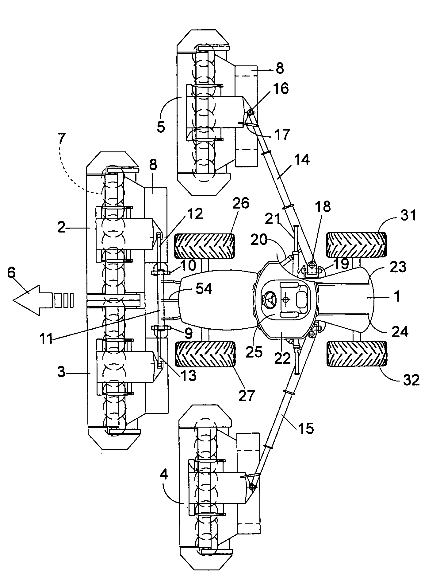
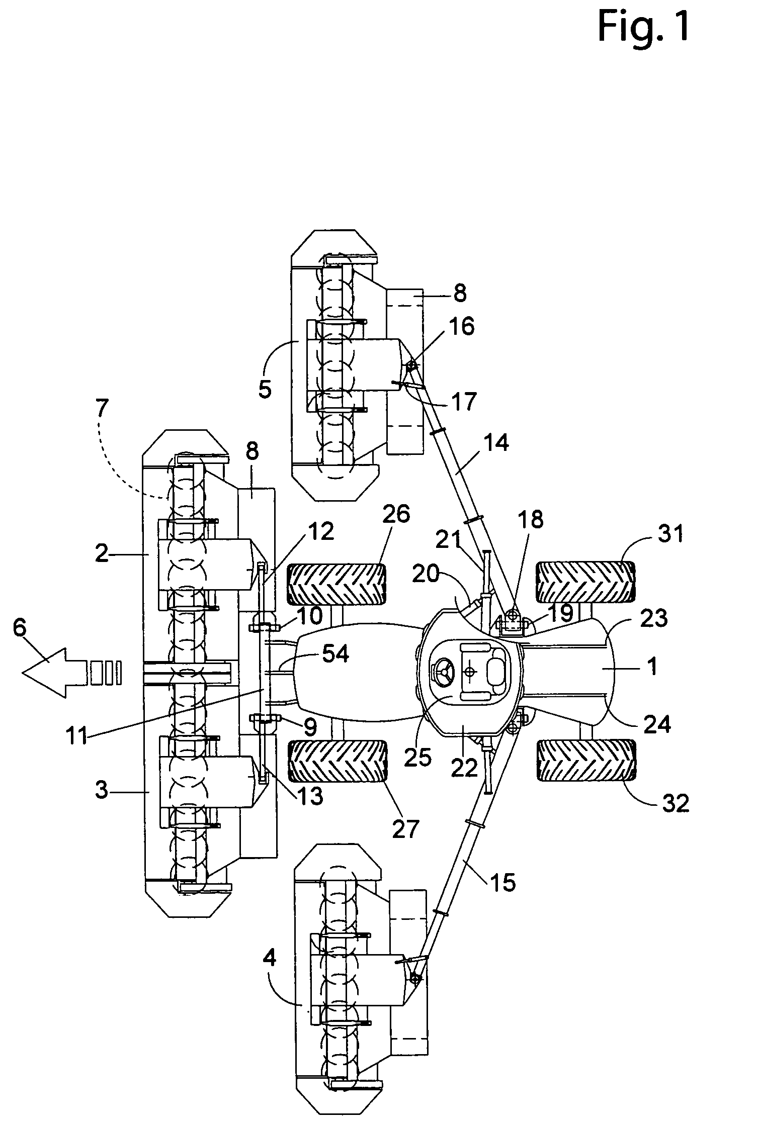
[0026]In the invention illustrated in FIG. 1, the carrier vehicle 1 has four working units: two frontal working units 2, 3 and two lateral working units 4, 5. In the work position illustrated in this FIG. 1, the direction of forward travel 6 represented by the arrow is the direction of work in the field.

[0027]In the example depicted, the agricultural machine is a mower-conditioner. For this purpose, the lateral 4, 5 and frontal 2, 3 units comprise at least one cutter bar 7, a plant conditioning device (not depicted in detail) situated partially above said cutter bar 7, and a device 8 for grouping these cut plants together into windrows.

[0028]Each cutter bar 7 consists, in a way known per se, of a cutter bar with cutting disks which are rotationally driven during work.

[0029]Various known devices for conditioning plants immediately after cutting and able to treat the plants in order to accelerate their drying time and shorten the delay before collection are conceivable, such as a roto...

second embodiment

[0049] illustrated in FIGS. 5 and 6, the carrier vehicle 34 comprises lateral working units 35, 36 always positioned level with the front wheels 37, 38 and along the axis of the axle connecting these two front wheels 37, 38. However, the telescopic arms 39, 40 are positioned in front of the driver's cab 41 and substantially perpendicular with respect to the carrier vehicle 34. These telescopic arms 39, 40 are articulated to the carrier vehicle 34 by means of substantially horizontal axes 42 situated in front of the driver's cab 41 and directed in the direction of forward travel 51. Said telescopic arms 39, 40 can be moved about these axes 42 using respective hydraulic rams 43 and 44 which are also connected to the carrier vehicle 34. The lateral working units 35 and 36 are articulated to the ends of these arms 39, 40 by respective axes 45, 46 that are substantially vertical in the work position, and can be pivoted about these axes 45, 46 using hydraulic rams 47, 48.

[0050]In this sec...


PUM


Abstract

An agricultural machine for cutting standing products comprising a carrier vehicle to which there are connected at least one frontal working unit positioned, during work and when viewed in a direction of forward travel of the carrier vehicle, forward of said carrier vehicle, and at least two lateral working units positioned, during work, on each side of a working area of said frontal working unit(s) and situated behind said frontal working unit(s) and being connected to carrier arms which are articulated to the carrier vehicle and allow said lateral working units to be moved into at least one work position situated level with the front wheels of the carrier vehicle and into a folded transport position, and the carrier vehicle comprising a driver's cab that can be moved toward the front or toward the rear of said carrier vehicle.

Description

BACKGROUND OF THE INVENTION[0001]1. Field of the Invention[0002]The present invention relates to an agricultural machine comprising a carrier vehicle and several working units intended to cut standing plants, said working units being connected to said carrier vehicle.[0003]2. Discussion of the Background[0004]A self-propelled mower comprising a carrier vehicle and three working units so as to cover a wide cutting area and improve the productivity of the machine exists in the prior art. More specifically, this mower comprises a frontal working unit and two lateral working units. This mower has a working width that can be as much as somewhat over 9 meters. In order to move it around on the roads, it has been necessary to provide a smaller-width transport position in which the lateral working units are pivoted vertically.[0005]In order to increase the working width still further and thus improve cutting performance, a greater number of working units has been envisaged. Patent FR 2 837 ...

Claims


Application Information

Patent Timeline
Patent Type & Authority Patents(United States)
IPC IPC(8): A01D43/00
CPCA01D75/303
Inventor HIRONIMUS, JEANNOT
Owner KUHN SA
Why Eureka
Try Eureka