Yarn feeder of yarn feeding device for weft knitting machine

a technology of yarn feeding device and yarn feeder, which is applied in the direction of weft knitting, knitting, textiles and papermaking, etc., can solve the problems of complicated and enlarged swinging mechanism of the yarn feeder, and achieve the effect of avoiding oversized tension stress, ensuring the swing width of the yarn feeder, and uniform stitches

Inactive Publication Date: 2009-06-09
SHIMA SEIKI MFG LTD +1
View PDF13 Cites 19 Cited by
  • Summary
  • Abstract
  • Description
  • Claims
  • Application Information

AI Technical Summary

Benefits of technology

[0017]According to the present invention, the feeder rod is formed of at least two members, one being an upper member activated by the entraining means and another one being a lower member composed of a yarn feeding port at its lower end, both of the members being arranged to be relatively slide each other in a vertical direction and provided with a push-up member forced upward respectively, and the upper member of the feeder rod is moved downward through the action of the entraining means, as well as the lower member of the feeder rod downward so that the yarn feeding port is set into the yarn feeding position, while the feeder rod is moved upward into the standby position by means of a regulation unit provided on a support member bearing the feeder rod so as to keep the lower member from rising against the action of a force caused by the push-up member, and the rise of the lower member of the feeder rod is resultantly made less than that of the upper member to limit the rise of the yarn feeding port in the standby position below the determined altitude. Therefore, the present invention resides not only in reliably obtaining the swing width of the yarn feeder but also in preventing from a larger altitude of the yarn feeding port in the standby position.
[0018]In this way, since the knitting yarn extended from the stitch of the end of the knitting region in the knitted fabric could be eliminated from oversized tension stress and clogging of stitch, it will advantageously lead to produce a knitted fabric having uniform stitches and high quality.
[0019]Moreover, unlike the generally employed case, the yarn feeder does not have to be largely slid to outside the knitting region, thus improving the productivity by reducing the sliding distance of the yarn feeder.
[0020]Additionally, in comparison with a conventional yarn feeder, even when the amount of swing of yarn feeders being in the same, the yarn feeding port in the present invention can be placed at a lower altitude. Therefore, even in case of a weft knitting machine of rough gauge or a needle-jumping-over knitting operation in which a large extent of swing of the yarn feeder is required, it can be advantageously kept in an ideal height apart from the yarn feeding port.

Problems solved by technology

However, if the amount of swing of the yarn feeder is increased, a swinging mechanism of the yarn feeder becomes enlarged and complicated.

Method used


Image

  • Yarn feeder of yarn feeding device for weft knitting machine
  • Yarn feeder of yarn feeding device for weft knitting machine
  • Yarn feeder of yarn feeding device for weft knitting machine

Examples


Embodiment Construction

[0021]An embodiment of a yarn feeding device for a weft knitting machine according to the present invention will be described referring to the drawings.

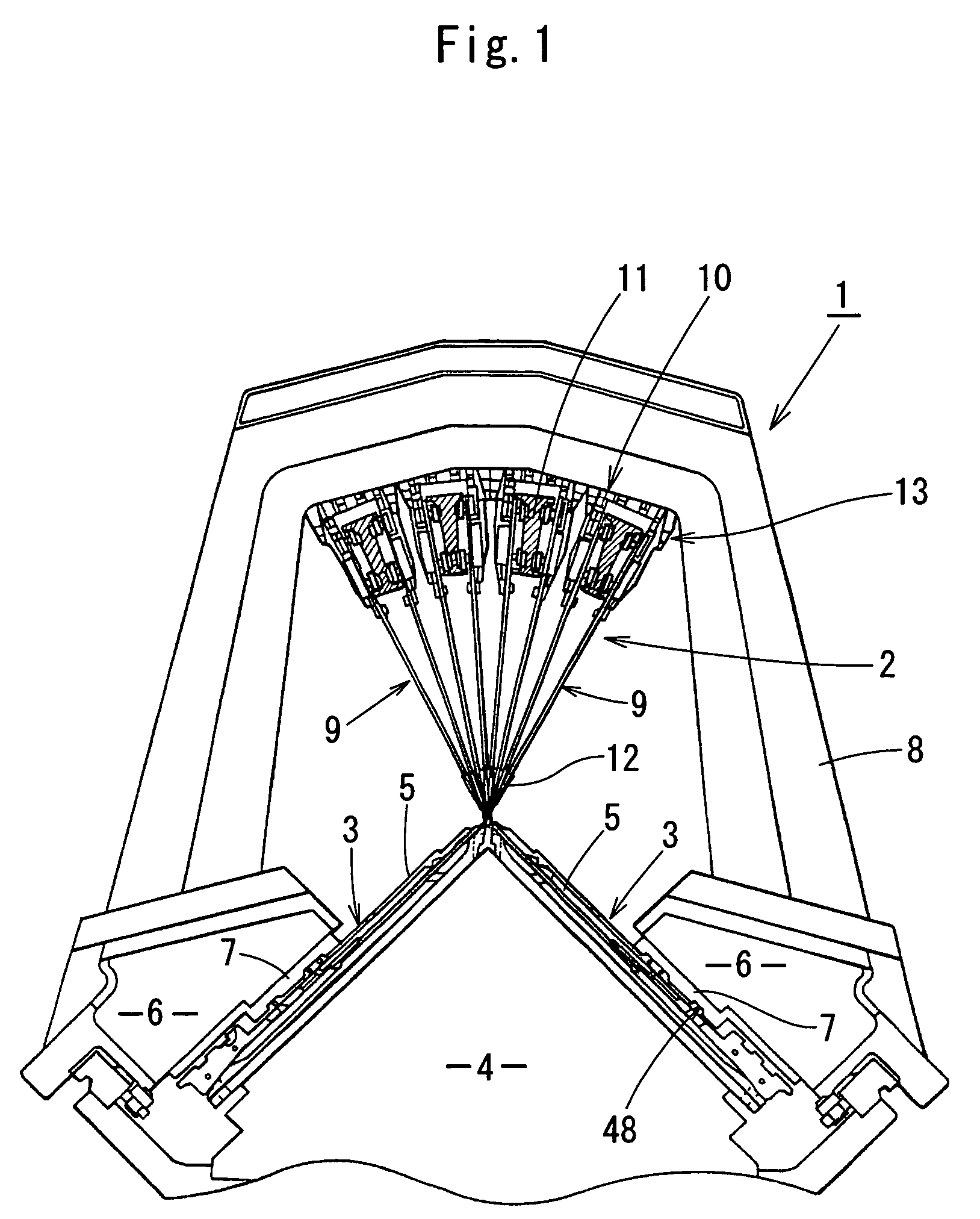
[0022]FIG. 1 is a lateral view of a weft knitting machine having a yarn feeding device including yarn feeders of the present invention, wherein a reference numeral 1 denotes the weft knitting machine in its entirety, and 2 denotes the yarn feeding device.

[0023]The weft knitting machine 1 has a pair of front and rear needle beds 3 disposed on a frame 4 in a fan shape with extreme ends thereof confronting each other, and each needle bed 3 has a plurality of knitting needles 5 thereon in parallel with each other so that they are movable back and forth.

[0024]A carriage 6 is disposed on an upper surface of each needle bed 3 so that it can be caused to reciprocate by a belt drive device (not shown). A bat 48 of each knitting needle 5 is operated by a knitting cam 7 attached to the carriage 6 as shown in the drawing so as to be advanced and...


PUM


Abstract

A yarn feeder includes a switching mechanism which presets a swing direction of the yarn feeding port after completion of a yarn feeding operation, and, after having completed a yarn feeding operation, changes over the swing of the yarn feeding port from one yarn feeding position to another standby position interlocking with the released selective operation of an entraining device, in which the switching mechanism includes a feeder rod having a yarn feeding port at its lower end, which is composed of at least two members, both of the members being arranged to relatively slide each other in a vertical direction and provided with a push-up member to force upward respectively. The switching mechanism includes a support member for bearing the yarn feeding rod being provided with a regulation unit for regulating the upward movement of the yarn feeding port in the determined standby position, wherein the rise of the yarn feeding port in the standby position is limited below the determined altitude by using the regulation unit.

Description

TECHNICAL FIELD[0001]The present invention relates to a yarn feeder of a yarn feeding device for a weft knitting machine, in which a yarn feeding port of the yarn feeder put on standby at an end portion of the knitting fabric or at a changed portion of the knitting pattern, for example, an intarsia knitting pattern, can be switched over to a position outside the fabric knitting region.BACKGROUND ART[0002]In general, a yarn feeder associated with a carriage to feed yarn to a needle in a needle bed for the knitting fabric is kept on a standby position outside the fabric knitting region.[0003]In this case, the position of a yarn is lowered proportionately as the yarn feeder greatly moves beyond the boundary with the adjoining knitting area so that the yarn feeding condition can be improved.[0004]Meanwhile, in case of an intarsia knitting operation, such a yarn feeder is released from the entraining device at a position exceeding the boundary with the boundary with the adjacent knitting...

Claims


Application Information

Patent Timeline
Patent Type & Authority Patents(United States)
IPC IPC(8): D04B15/56
CPCD04B7/26D04B15/56D04B15/54
Inventor MIYAMOTO, MASAKI
Owner SHIMA SEIKI MFG LTD
Why Eureka
Try Eureka