Device for measuring the mass rate of flow having a bobbin for a magnetic coil made from a material having a specific thermal conductivity

a technology of magnetic coil and mass rate, which is applied in the direction of direct mass flowmeter, electromagnet, and non-armature electric motors, etc., can solve the problems of disadvantageous procedure with respect to its relatively high cost and efficiency reduction, and achieve the effect of efficient and high-power applications

Active Publication Date: 2009-06-09
KRONE GMBH
View PDF12 Cites 3 Cited by
  • Summary
  • Abstract
  • Description
  • Claims
  • Application Information

AI Technical Summary

Benefits of technology

[0008]Accordingly, a primary object of the present invention is to devise a device for measuring the mass rate of flow which operates according to the Coriolis principle and which is efficiently suitable for high power applications without leading to overly high temperatures of the magnet coil which is designed for vibration excitation and / or for detection of vibrations of the measurement tube.
[0010]Therefore the invention takes a completely new approach by the magnet coil itself specifically the bobbin, being made such that the resulting heat can be easily dissipated to the vicinity without farther contrivances. In contrast to conventional technology, this is much more economical, and furthermore based on possible omission of the heat sink such as a metallic cooling sheet, generation of eddy currents can be avoided so that the efficiency of the magnet coil is improved.
[0015]Finally, according to one preferred development of the invention, it is also provided that the magnet coil is potted with a potting material to further improve heat dissipation. The potting materials are preferably casting resins which, in addition to good heat dissipation, also ensure reliable electrical insulation.

Problems solved by technology

However, this procedure is disadvantageous with respect to its relatively high costs and reduced efficiency as a result of formation of eddy currents in the metallic heat sink.

Method used


Image

  • Device for measuring the mass rate of flow having a bobbin for a magnetic coil made from a material having a specific thermal conductivity
  • Device for measuring the mass rate of flow having a bobbin for a magnetic coil made from a material having a specific thermal conductivity
  • Device for measuring the mass rate of flow having a bobbin for a magnetic coil made from a material having a specific thermal conductivity

Examples


Embodiment Construction

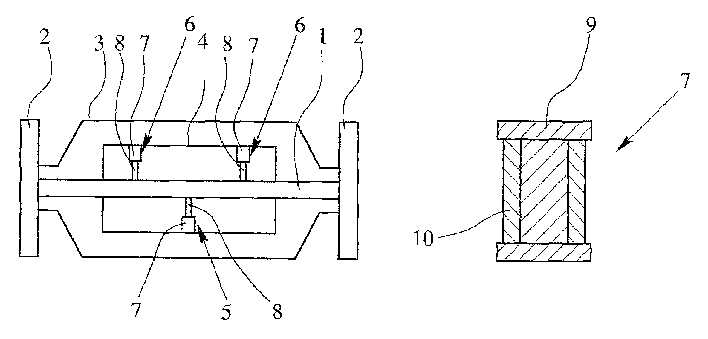
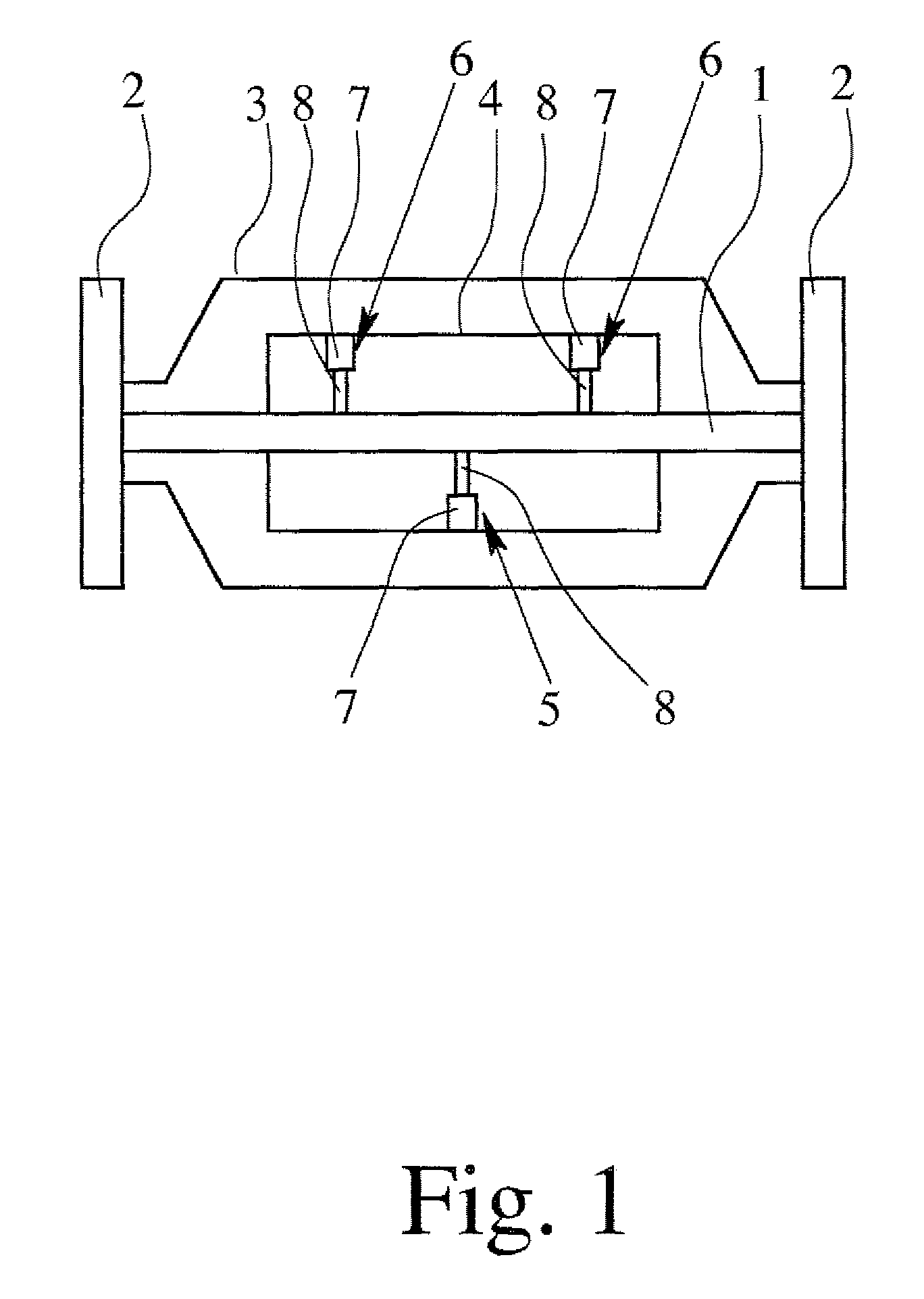
[0019]FIG. 1 schematically shows a device for measuring the mass rate of flow using the Coriolis principle according to a preferred exemplary embodiment of the invention with a single straight measurement tube 1. The measurement tube 1 has a flange 2 on each of its two ends, with which the measurement tube 1 can be installed in a pipeline system, which is not further shown. The measurement tube 1 is located within a housing 3 in which there is an inner cylinder 4. Between the inner cylinder 4 and the measurement tube 1, there are a vibration generator 5 and two vibration sensors 6.

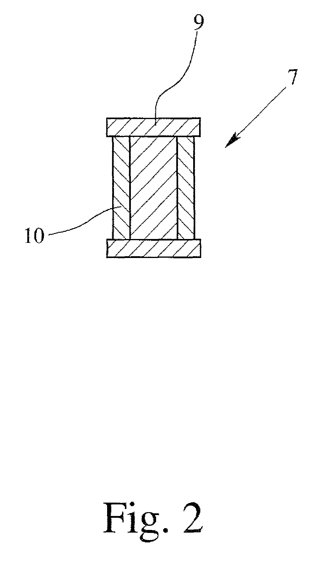
[0020]The vibration generator 5 and the two vibrations sensors 6 each have a magnet coil 7 and a magnet 8 located in the magnet coil 7. As initially described, the respective magnet coil 7, when it is exposed to current, generates a magnetic field; this results in a force being exerted on the magnet 8 which is located within the magnet coil 7. The vibration generator 5 is operated in this way to excite the...


PUM


Abstract

A device for measuring the mass rate of flow which operates according to the Coriolis principle, with a measurement tube (1) and a magnet coil (7) of a bobbin (9) and a winding (10) attached to it for exciting and / or detecting vibrations of the measurement tube (1). The bobbin (9) of the magnet coil (7) has a specific thermal conductivity of at least 1 W / (K m). This enables the heat which forms in the magnet coil (7) to be efficiently dissipated to the surrounding vicinity without cooling elements, such as cooling fins, being necessary. In this way, the efficiency of the device for measuring the mass rate of flow using the Coriolis principle is altogether improved.

Description

BACKGROUND OF THE INVENTION[0001]1. Field of the Invention[0002]The invention relates to a device for measuring the mass rate of flow which works according to the Coriolis principle, with a measurement tube and a vibration generator and / or a vibration sensor for exciting and detecting vibrations of the measurement tube, the vibration generator and the vibration sensor having a magnet coil with a bobbin and a winding attached to it.[0003]2. Description of Related Art[0004]Devices for measuring the mass rate of flow using the Coriolis principle are well known from the prior art. In this connection, there are devices with only a single measurement tube or with several, often two parallel measurement tubes, and the measurement tube or measurement tubes can be made straight or looped. Devices for measuring the mass rate of flow using the Coriolis principle require that the measurement tube be sent into vibration and that the vibrations which result when flow takes place through the measu...

Claims


Application Information

Patent Timeline
Patent Type & Authority Patents(United States)
IPC IPC(8): G01F1/84
CPCG01F1/8422G01F1/849H01F7/20H01F27/22
Inventor DAVIES, LAWRENCE
Owner KRONE GMBH
Why Eureka
Try Eureka