Output calibration apparatus and output calibration method for NOx sensor

a technology of output calibration and nox sensor, which is applied in the direction of engine testing, structural/machine measurement, electrical control, etc., can solve the problems of no technique suitable for calibrating the gain of the nox sensor, and the output value to deviate gradually from the one obtained

Active Publication Date: 2011-11-15
TOYOTA JIDOSHA KK
View PDF21 Cites 6 Cited by
  • Summary
  • Abstract
  • Description
  • Claims
  • Application Information

AI Technical Summary

Benefits of technology

[0018]Thus, the offset can be suitably calibrated, and the gain is calibrated with a reference point or a zero point accurately set. Consequently, the gain can be more accurately calibrated.
[0020]In particular, a growing demand for an emission reduction has recently led to a demand for an increase in the accuracy of detection of NOx in a low NOx-concentration region. Then, calibrating the gain for each of the plurality of divided regions allows the gain to be accurately obtained for each region. This enables a drastic improvement in the accuracy with which NOx is detected in each region, particularly in the low-concentration region.
[0023]At least after execution of the calibration of the gain of the downstream NOx sensor, the correlation between the output from the downstream NOx sensor and the NOx concentration is accurate. Furthermore, during non-execution of the fuel cut, NOx is present in exhaust gas. During non-execution of the urea addition, the possible adverse effects of ammonia resulting from the urea are inhibited. Hence, exhaust gas of the same NOx concentration can be supplied to the upstream NOx sensor and the downstream NOx sensor. Consequently, the gain of the upstream NOx sensor can be suitably calibrated by comparing the outputs from the two sensors with each other.
[0028]The present invention is very effective for suitably calibrating the gain of the Nox sensor.

Problems solved by technology

However, temporal changes or the like may cause the output value to deviate gradually from the one obtained when the sensor is new.
However, no technique suitable for calibrating the gain of the NOx sensor has been developed, and appropriate measures have been expected to be urgently developed.

Method used


Image

  • Output calibration apparatus and output calibration method for NOx sensor
  • Output calibration apparatus and output calibration method for NOx sensor
  • Output calibration apparatus and output calibration method for NOx sensor

Examples


Embodiment Construction

[0037]The best mode for carrying out the present invention will be described below with reference to the drawings.

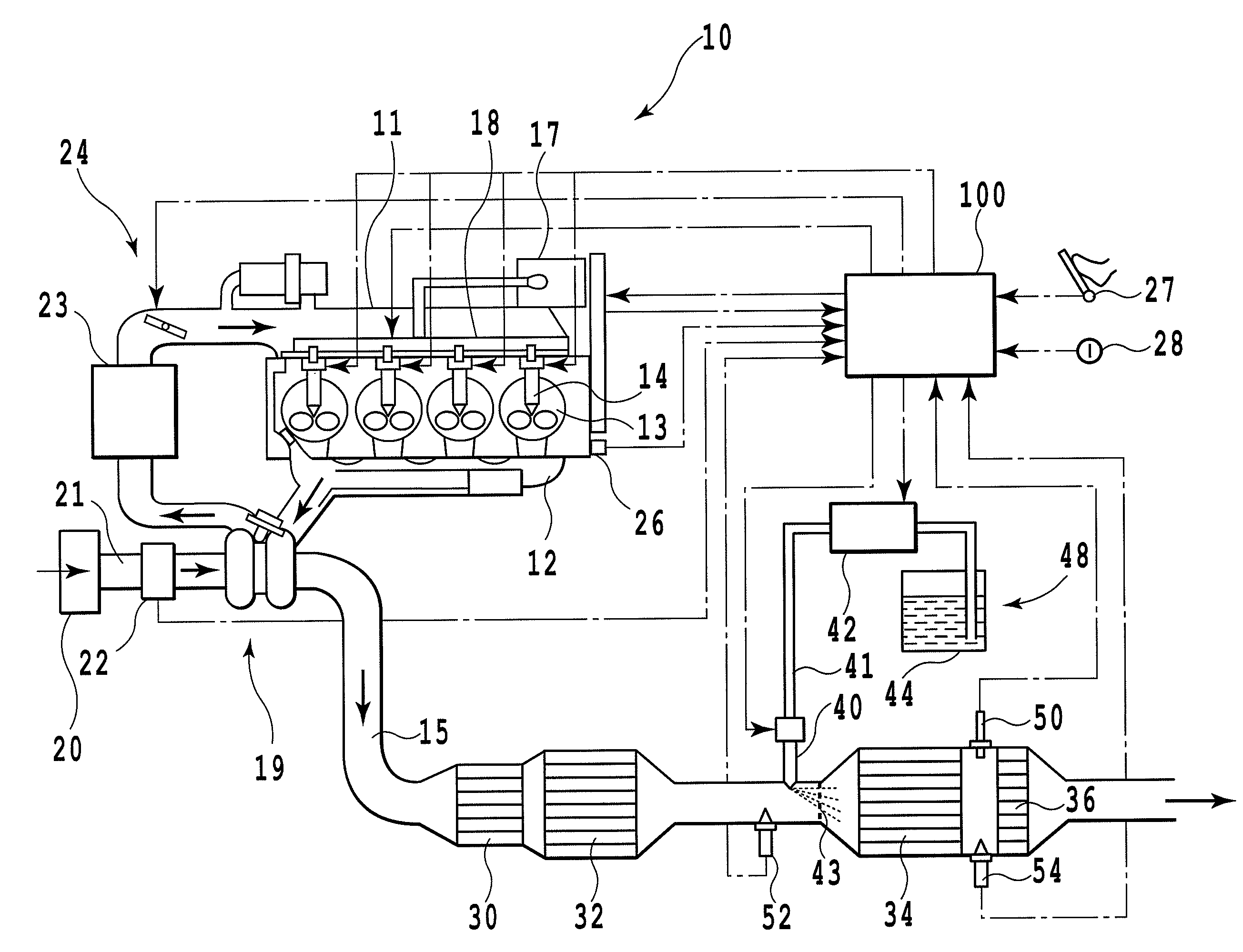
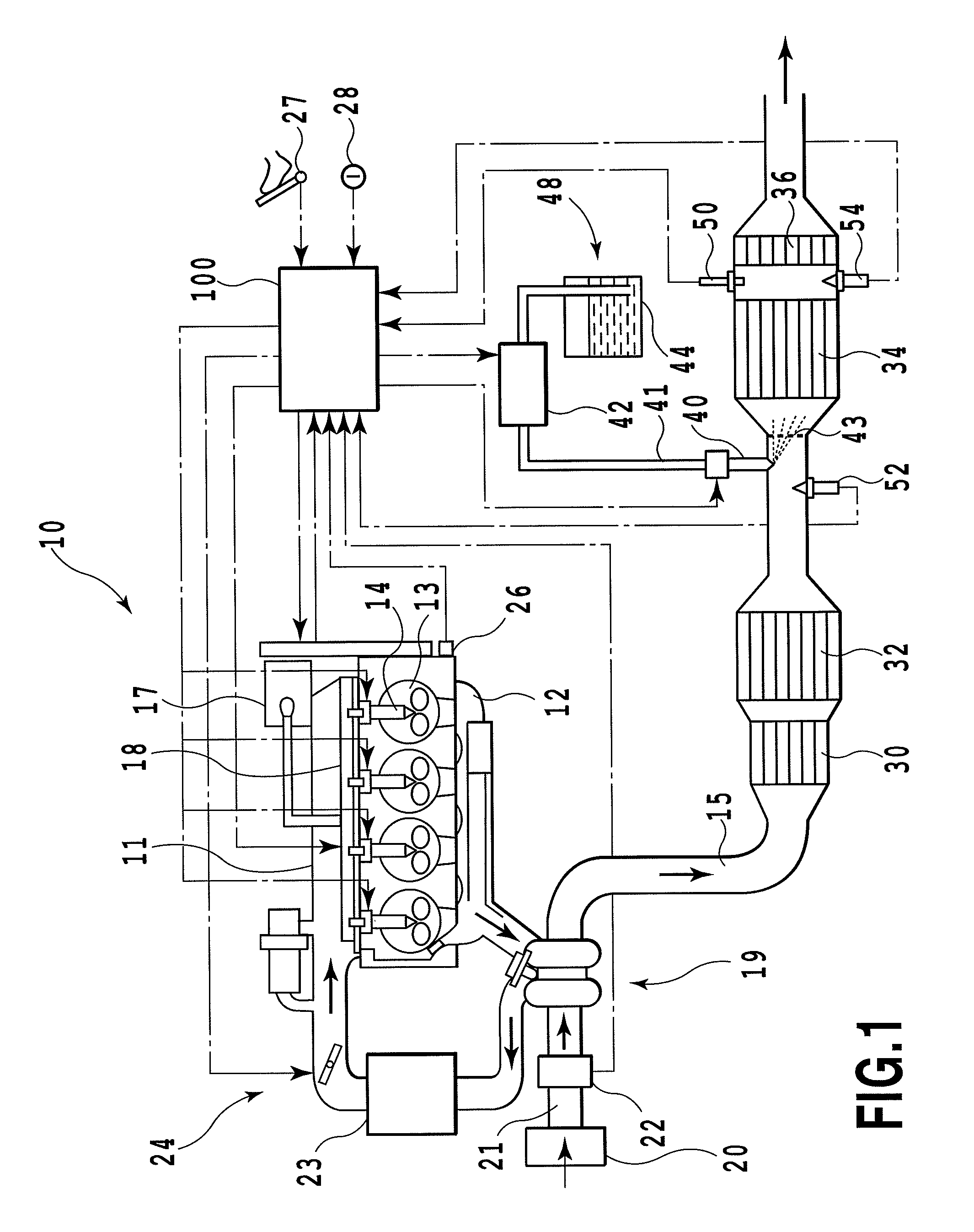
[0038]FIG. 1 is a schematic diagram of the system of an internal combustion engine according to an embodiment of the present invention. In FIG. 1, reference numeral 10 denotes a compression ignition internal combustion engine for automobiles, that is, a diesel engine. Reference numeral 11 denotes an intake manifold that is in communication with an intake port. Reference numeral 12 denotes an exhaust manifold that is in communication with an exhaust port. Reference numeral 13 denotes a combustion chamber. In the present embodiment, fuel from a fuel tank (not shown in the drawings) is supplied to a high-pressure pump 17. The high-pressure pump 17 then pumps the fuel to a common rail 18, in which the fuel is accumulated at a high pressure. The high-pressure fuel in the common rail 18 is injected and fed into the combustion chamber 13 through an injector 14. Exhaust gas from...


PUM


Abstract

An output calibration apparatus for an NOx sensor according to the present invention includes a urea addition valve provided in an exhaust passage in an internal combustion engine to allow urea to be added to inside of the exhaust passage, and an NOx sensor provided at least downstream of the urea addition valve, the NOx sensor being capable of detecting not only an NOx concentration but also an ammonia concentration. The output calibration apparatus executes fuel cut on the internal combustion engine, and calibrates a gain of the NOx sensor based on ammonia obtained from the urea added via the urea addition valve during execution of the fuel cut. The ammonia obtained from the urea added during execution of the fuel cut is used as standard gas to calibrate the gain of the NOx sensor.

Description

TECHNICAL FIELD[0001]The present invention relates to an output calibration apparatus and an output calibration method for an NOx sensor, and in particular, to an apparatus and a method suitable for calibrating the gain of an NOx sensor provided in an exhaust passage in an internal combustion engine.BACKGROUND ART[0002]In general, an NOx catalyst configured to clean NOx (nitrogen oxide) contained in exhaust gas is known as an exhaust purifying apparatus located in an exhaust system in an internal combustion engine such as a diesel engine. Various types of NOx catalysts are known. In particular, an NOx catalyst of selective reduction type is well known which continuously reduces and removes NOx by addition of a reducing agent. The reducing agent is commonly used in the form of an aqueous solution of urea. The aqueous solution of urea is ejected and fed from the upstream side of the catalyst. Then, the aqueous solution of urea receives heat from the exhaust and the catalyst and is thu...

Claims


Application Information

Patent Timeline
Patent Type & Authority Patents(United States)
IPC IPC(8): G01M15/00
CPCF02D41/123F02D41/146F02D41/1461F02D41/2432F02D41/2474F02D2041/1468
Inventor MURASE, NAO
Owner TOYOTA JIDOSHA KK
Why Eureka
Try Eureka