Fuel cell module

a fuel cell module and fuel cell technology, applied in the direction of fuel cells, solid electrolyte fuel cells, electrical equipment, etc., can solve the problems of low reliability of gas sealing performance, low system efficiency, high cost of system, etc., to improve power generation efficiency, improve fuel utilization ratio, and high steam reforming efficiency

Active Publication Date: 2017-07-04
HONDA MOTOR CO LTD
View PDF14 Cites 0 Cited by
  • Summary
  • Abstract
  • Description
  • Claims
  • Application Information

AI Technical Summary

Benefits of technology

[0013]Further, since some of the fuel gas produced in the reformer 3a is used in hydrodesulfurization, in effect, the amount of fuel supplied to the fuel cell main body 4a is decreased. Further, since the fuel blower 1a is configured to allow the hydrogen to flow through the fuel blower 1a, cost of the system is high, and the reliability of the gas sealing performance is low.
[0022]Accordingly, with the compact structure, improvement in the power generation efficiency is achieved, and it becomes possible to perform suitable hydrodesulfurization efficiently.

Problems solved by technology

Accordingly, the system efficiency is low.
Further, since the fuel blower 1a is configured to allow the hydrogen to flow through the fuel blower 1a, cost of the system is high, and the reliability of the gas sealing performance is low.
Further, in the above conventional technique 2, since the first reformer 2b and the second reformer 4b are provided internally, cost of the system is high, and the system is large as a whole.
Moreover, the efficiency tends to be lowered by partial oxidation reaction, and the system efficiency may be lowered undesirably.
Furthermore, in the above conventional technique 3, as in the case of the conventional technique 1, it is required to heat hydrodesulfurization material to the temperature in a range of about 250° C. to 500° C. Therefore, the system efficiency is low.

Method used


Image

  • Fuel cell module
  • Fuel cell module
  • Fuel cell module

Examples


Embodiment Construction

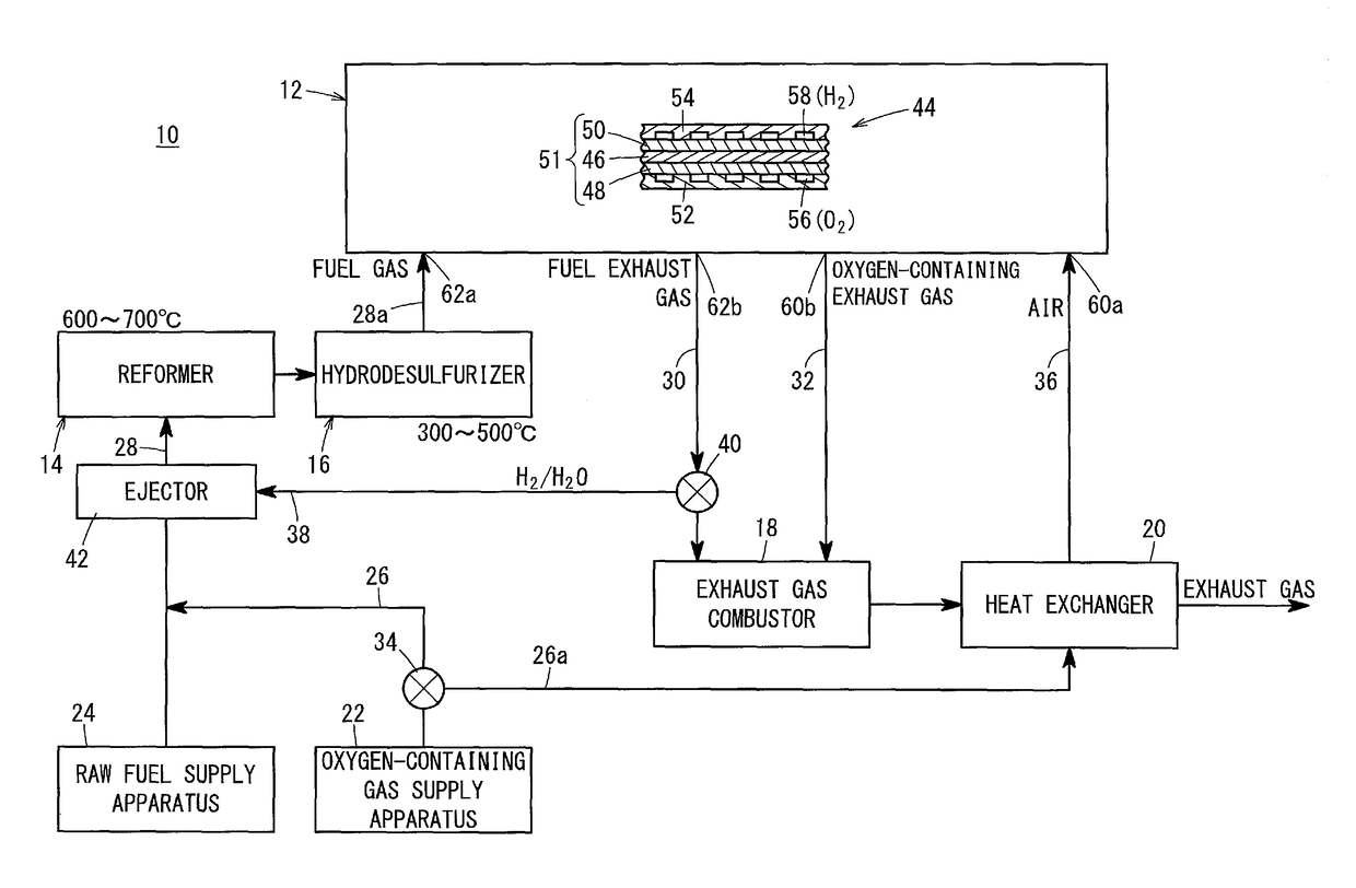
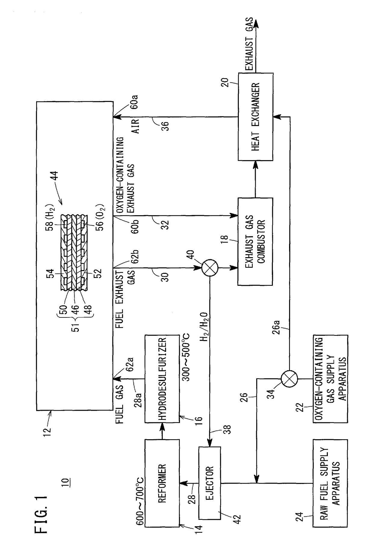
[0034]A fuel cell module 10 according to a first embodiment of the present invention shown in FIG. 1 is used in various applications, including stationary, in-vehicle, and mobile applications.

[0035]The fuel cell module 10 includes a fuel cell stack 12, a reformer 14, a hydrodesulfurizer 16, an exhaust gas combustor 18, and a heat exchanger 20. An oxygen-containing gas supply apparatus 22 for supplying an oxygen-containing gas and a raw fuel supply apparatus 24 for supplying a raw fuel (e.g., city gas) are connected to the fuel cell module 10.

[0036]The oxygen-containing gas supply apparatus 22 is connected to the reformer 14 through an oxygen-containing gas supply channel 26, and the raw fuel supply apparatus 24 is connected to the reformer 14 through a fuel gas supply channel 28. In the illustrated embodiment, the oxygen-containing gas supply channel 26 is connected to a position somewhere in the fuel gas supply channel 28. Alternatively, the oxygen-containing gas supply channel 26 ...


PUM

PropertyMeasurementUnit
temperatureaaaaaaaaaa
operating temperatureaaaaaaaaaa

Abstract

A fuel cell module includes a fuel cell stack, a reformer, and a hydrodesulfurizer. A fuel gas is supplied to the fuel cell stack through a fuel gas supply channel, and the reformer and the hydrodesulfurizer are provided for the fuel gas supply channel. A fuel exhaust gas is discharged from the fuel cell stack into a fuel exhaust gas channel, and a recycling channel is connected to the fuel exhaust gas channel, for circulating some of the fuel exhaust gas to return to a position of the fuel gas supply channel, the position provided upstream of the reformer and the hydrodesulfurizer.

Description

CROSS-REFERENCE TO RELATED APPLICATION[0001]This application is based upon and claims the benefit of priority from Japanese Patent Application No. 2014-175607 filed on Aug. 29, 2014, the contents of which are incorporated herein by reference.BACKGROUND OF THE INVENTION[0002]Field of the Invention[0003]The present invention relates to a fuel cell module including a fuel cell stack formed by stacking a plurality of fuel cells for generating electrical energy by electrochemical reactions of a fuel gas and an oxygen-containing gas.[0004]Description of the Related Art[0005]In general, a solid oxide fuel cell (SOFC) employs a solid electrolyte. The solid electrolyte is an oxide ion conductor such as stabilized zirconia. The solid electrolyte is interposed between an anode and a cathode to form an electrolyte electrode assembly (also referred to as MEA). The electrolyte electrode assembly is sandwiched between separators (bipolar plates). In use, generally, predetermined numbers of the ele...

Claims


Application Information

Patent Timeline
Patent Type & Authority Patents(United States)
IPC IPC(8): H01M8/06H01M8/12H01M8/0612H01M8/0662H01M8/04089H01M8/04014H01M8/124
CPCH01M8/0612H01M8/04022H01M8/04097H01M8/0675H01M2008/1293Y02E60/50
Inventor TSUKAMOTO, KEIJINANGO, AYAKAMIZUNO, JUN
Owner HONDA MOTOR CO LTD
Why Eureka
Try Eureka