Tillage apparatus having flexible frame and weight distribution system

a tillage apparatus and flexible technology, applied in the field of tillage apparatus, can solve the problems of uneven weight distribution of known seeding and/or compaction devices, uneven seed insertion, uneven soil compaction in seeded areas, etc., and achieve the effect of improving weight distribution

Active Publication Date: 2009-06-09
CNH IND CANADA
View PDF28 Cites 3 Cited by
  • Summary
  • Abstract
  • Description
  • Claims
  • Application Information

AI Technical Summary

Benefits of technology

[0011]The foregoing needs are met by a tillage apparatus according to the invention. The tillage apparatus includes a flexible frame such that rear press wheels can more closely follow the contours of the ground thereby providing more even seed insertion and soil compaction. The tillage apparatus also provides improved weight distribution for the rear press wheels thereby providing more even seed insertion and soil compaction. In addition, the tillage apparatus provides adjustable weight transfer to the rear press wheels thereby providing more even seed insertion and soil compaction.
[0012]In one aspect, the tillage apparatus includes a frame including a forward frame section having a plurality of tillers and a rearward frame section having a plurality of tillers, and at least two rotatable land wheels supporting the frame. At least one wheel support gang is attached to the rearward frame section, and a plurality of rotatable press wheels are suspended from each wheel support gang. The forward frame section has an axis in a direction of movement of the apparatus when tilling the field and the rearward frame section can pivot radially with respect to the axis of the forward frame section such that a pitch of the forward frame section follows a contour of the field encountered by the land wheels and a pitch of the rearward frame section follows a contour of the field encountered by the press wheels when the tilling the field. Thus, the pitch of the forward frame section is controlled by land wheels and the pitch of the rearward frame section is controlled by press wheels. The flexible frame is provided so that rear press wheels can more closely follow the contours of the ground thereby providing more even seed insertion and soil compaction.
[0016]In another aspect, the tillage apparatus includes a frame including a rearward frame section having a plurality of tillers. A crossbar is attached to the rearward frame section, and the crossbar has an axis in a direction of movement of the apparatus when tilling the field. An outermost wheel support gang is attached to the crossbar such that the outermost wheel support gang can pivot radially with respect to the axis of the crossbar. Rotatable press wheels are suspended from the outermost wheel support gang. A linkage assembly is connected to the rearward frame section and to the crossbar inward from the outermost wheel support gang. An inner wheel support gang is attached to a pivoting mounting bracket of the linkage assembly such that the inner wheel support gang can pivot radially with respect to the axis of the crossbar and can pivot in the direction of the axis of the crossbar. A plurality of rotatable press wheels are suspended from the inner wheel support gang. When the apparatus is pulled across the field during tilling, the press wheels of the outermost wheel support gang follow a contour of the field and the inner wheel support gang pivots radially with respect to the axis of the crossbar and pivots away or toward the direction of the axis of the crossbar such that the press wheels of the inner wheel support gang follow a contour of the field. Thus, the tillage apparatus provides improved weight distribution for the rear press wheels thereby providing more even seed insertion and soil compaction.
[0020]The mounting bracket may include means for adjusting the spacing between a junction of the compression strut and the mounting bracket and a junction of the frame arm and the mounting bracket thereby adjusting distribution of loads on the inner wheel support gang and the outermost wheel support gang and the second outermost wheel support gang when the apparatus is pulled across the field.
[0021]In yet another aspect, the tillage apparatus includes a frame having a boom, a plurality of tillers, a forward frame section, and a rearward frame section connected to the forward frame section. At least one wheel support gang is attached to the rearward frame section, and rotatable press wheels are suspended from each wheel support gang. The apparatus includes a weight transfer device including a linkage connecting the boom and the forward frame section. The weight transfer device includes biasing means pivotally connected to the forward frame section and to the linkage. The biasing means distributes weight from the boom to the forward frame section to the rearward frame section and to the press wheels by applying a downward force on the linkage. The forward frame section can be moved from a raised position in which the biasing means does not apply a downward force on the linkage to a lower working position in which the biasing means applies a downward force on the linkage.
[0024]Thus, a mechanism is provided whereby the weight of the front boom can be adjustably transferred to rear press wheels by creating torsional force about their connecting pivot.

Problems solved by technology

Some known seeding and / or compaction devices suffer from uneven weight distribution on the land wheels and rear press wheels.
This can cause seed insertion which is uneven and / or deeper or shallower than desired, and uneven soil compaction in seeded areas.
Some known seeding and / or compaction devices are also disadvantageous in that the rear press wheels are unable to independently follow the contours of the ground.
This can result in uneven compaction in tilled areas.

Method used


Image

  • Tillage apparatus having flexible frame and weight distribution system
  • Tillage apparatus having flexible frame and weight distribution system
  • Tillage apparatus having flexible frame and weight distribution system

Examples


Embodiment Construction

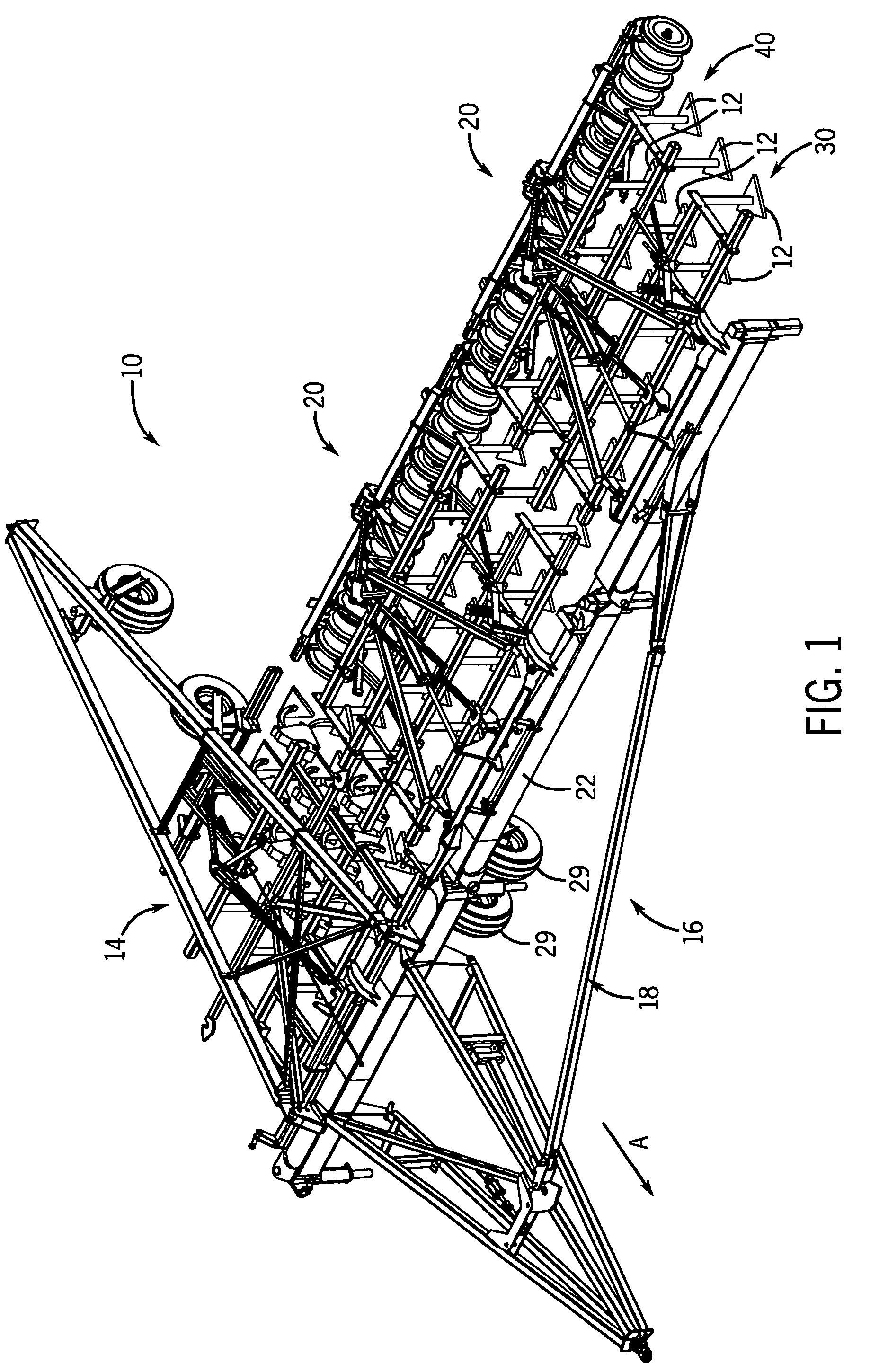
[0035]Looking at FIG. 1, there is shown a shank type seed drill apparatus 10 having a central portion 14 and having a left wing portion 16 having two frames 20. The apparatus 10 has a right wing portion (not shown) that is a mirror image of the left wing portion 16. The left wing portion 16 may be upwardly folded for transport using arm 18. Likewise, the right wing portion may be upwardly folded for transport. Each frame 20 includes a forward frame section 30 with tillers 12 and a rearward frame section 40 with tillers 12. The apparatus 10 is connected to a tractor in a conventional manner and has an axis A in a direction of movement of the apparatus 10 when tilling a field.

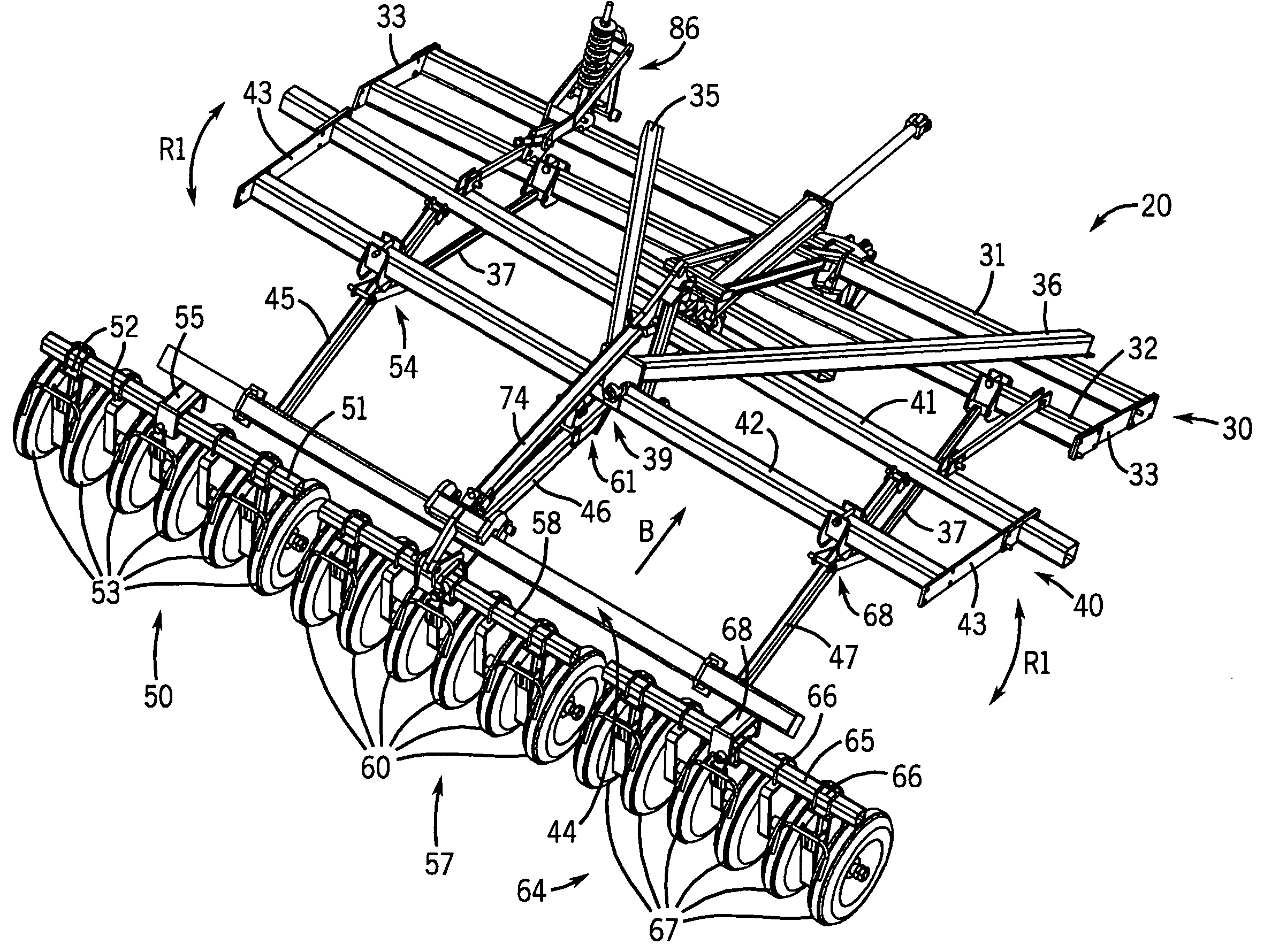
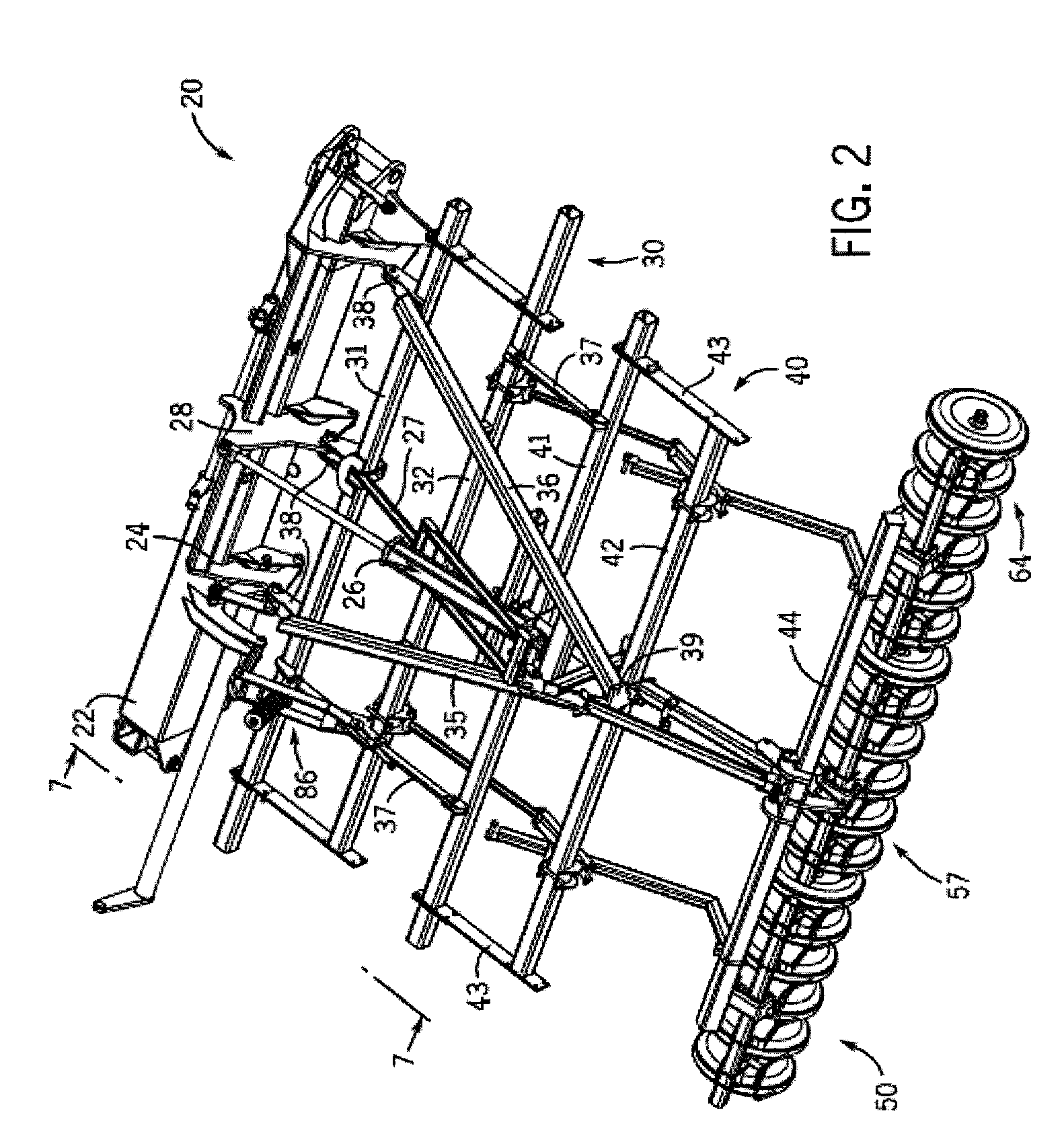
[0036]In FIGS. 2 and 3, there is shown one frame 20 of the apparatus 10, with the tillers removed for clarity. The forward frame section 30 includes a front transverse tube 31 and a rear transverse tube 32 connected by supports 33. Angled frame members 35 and 36 are connected to the top of the front transverse tu...


PUM


Abstract

A tillage apparatus including a frame having tillers, land wheels supporting the frame, and press wheels on the frame is disclosed. In one form, the frame has a forward section and a rearward section supporting the press wheels. The rearward section can pivot radially with respect to the direction of movement of the forward section. In another form, the frame includes a linkage assembly connected to the rearward section. An inner wheel support gang having press wheels is attached to a pivoting mounting bracket of the linkage assembly such that the inner wheel support gang can pivot vertically. In another form, the apparatus includes a weight transfer device including a linkage connecting a boom and the forward section. A biasing means pivotally connected to the forward section and to the linkage distributes weight from the boom to the forward section to the rearward section and to the press wheels.

Description

CROSS-REFERENCES TO RELATED APPLICATIONS[0001]Not Applicable.STATEMENT REGARDING FEDERALLY SPONSORED RESEARCH[0002]Not Applicable.BACKGROUND OF THE INVENTION[0003]1. Field of the Invention[0004]The present invention relates to an agricultural tillage apparatus including rear press wheels, and more particularly, the invention pertains to an agricultural tillage apparatus that provides improved frame flexibility such that the rear press wheels can more closely follow the contours of the ground, that provides improved weight distribution for the rear press wheels, and that provides adjustable weight transfer to the rear press wheels.[0005]2. Description of the Related Art[0006]Typical agricultural seeders are wheeled implements which are towed by agricultural work vehicles such as tractors. A seeder has a frame structure which has containers for seeds and a number of seed insertion devices such as shank type seed drills. The seed drills are arranged in horizontal rows to provide unifor...

Claims


Application Information

Patent Timeline
Patent Type & Authority Patents(United States)
IPC IPC(8): A01B49/00
CPCA01B23/043A01B29/06A01B63/145
Inventor FRIGGSTAD, TERRANCE A.
Owner CNH IND CANADA
Why Eureka
Try Eureka