Diffuse reflector for a liquid crystal display device

a liquid crystal display device and diffuse reflector technology, applied in the direction of mirrors, instruments, mountings, etc., can solve the problems of difficult to improve the quality of the image to be displayed by the liquid crystal display device, and achieve the effect of improving the quality of the image displayed, easy to adjust the reflection direction, and constant width

Inactive Publication Date: 2009-06-09
TPO HONG KONG HLDG
View PDF18 Cites 0 Cited by
  • Summary
  • Abstract
  • Description
  • Claims
  • Application Information

AI Technical Summary

Benefits of technology

[0013]In a method of forming a reflector member according to the invention, the first film is formed and the plurality of holes are formed in the first film in order to form the underlayer. The plurality of holes are formed in the first film in such a way that the plurality of partitions are formed in the first film. Each of the plurality of partitions has a substantially constant width and separates adjacent holes of the plurality of holes. Further, the widths of at least several of the plurality of partitions are substantially equal to each other. Since the underlayer is provided with the first film having the partitions, a shape of the reflector member formed on the underlayer is influenced by shapes of the partitions, so that an adjustment of size etc. of the partitions makes it possible to adjust a reflection direction of light reflected by the reflective member. Therefore, if the reflective member is applied to a liquid crystal display device for example, it is possible to improve a quality of image displayed by the liquid crystal display.
[0014]In a method of forming a reflector member according to the present invention, it is preferable that the widths of the at lease several of the plurality of partitions are in the range from 3 μm to 6 μm inclusive. By setting the width of the partitions in the range described above, it is easily possible to adjust a reflection direction of light reflected by the reflective member.
[0015]In a method of forming a reflector member according to the present invention, it is preferable that, in the step of forming a plurality of holes, the plurality of holes are formed in the first film in such a way that a plurality of hole sets are formed in the first film, wherein each of the hole sets comprises one first hole and at least three second holes of the plurality of holes; and wherein the at least three second holes are arranged around the first hole. By forming the plurality of hole sets, a number of holes can be formed in the first film at high density. By forming the number of holes in the first film, it is possible to decrease a specular reflection component of light reflected by the reflector member.
[0016]In a method of forming a reflector member according to the present invention, it is preferable that the number of the second holes is seven. If a liquid crystal display device is provided with the reflector member in this method, it is possible to prevent an interference of light reflected by the reflector member of the liquid crystal display device effectively.
[0017]In a method of forming a reflector member according to the present invention, it is preferable that the step of forming the first film is a step of forming a photosensitive film, and that the step of forming the plurality of holes is a step of patterning the photosensitive film in such a way that the plurality of partitions are formed in the photosensitive film, each of the plurality of holes having a substantially constant width and separating adjacent holes of the plurality of holes, wherein the widths of at lease several of the plurality of partitions are substantially equal to each other. If the photosensitive film is formed as the first film and the photosensitive film is patterned, it is easily possible to provide the photosensitive film with the partitions.

Problems solved by technology

It is possible to provide the reflective electrode or the reflector with recesses or projections by patterning the photosensitive resin in the predetermined form, but if the photosensitive resin is simply patterned it is difficult to improve the quality of the image to be displayed by the liquid crystal display device.

Method used


Image

  • Diffuse reflector for a liquid crystal display device
  • Diffuse reflector for a liquid crystal display device
  • Diffuse reflector for a liquid crystal display device

Examples


Embodiment Construction

)

[0049]Hereinafter, an embodiment of the present invention will be described.

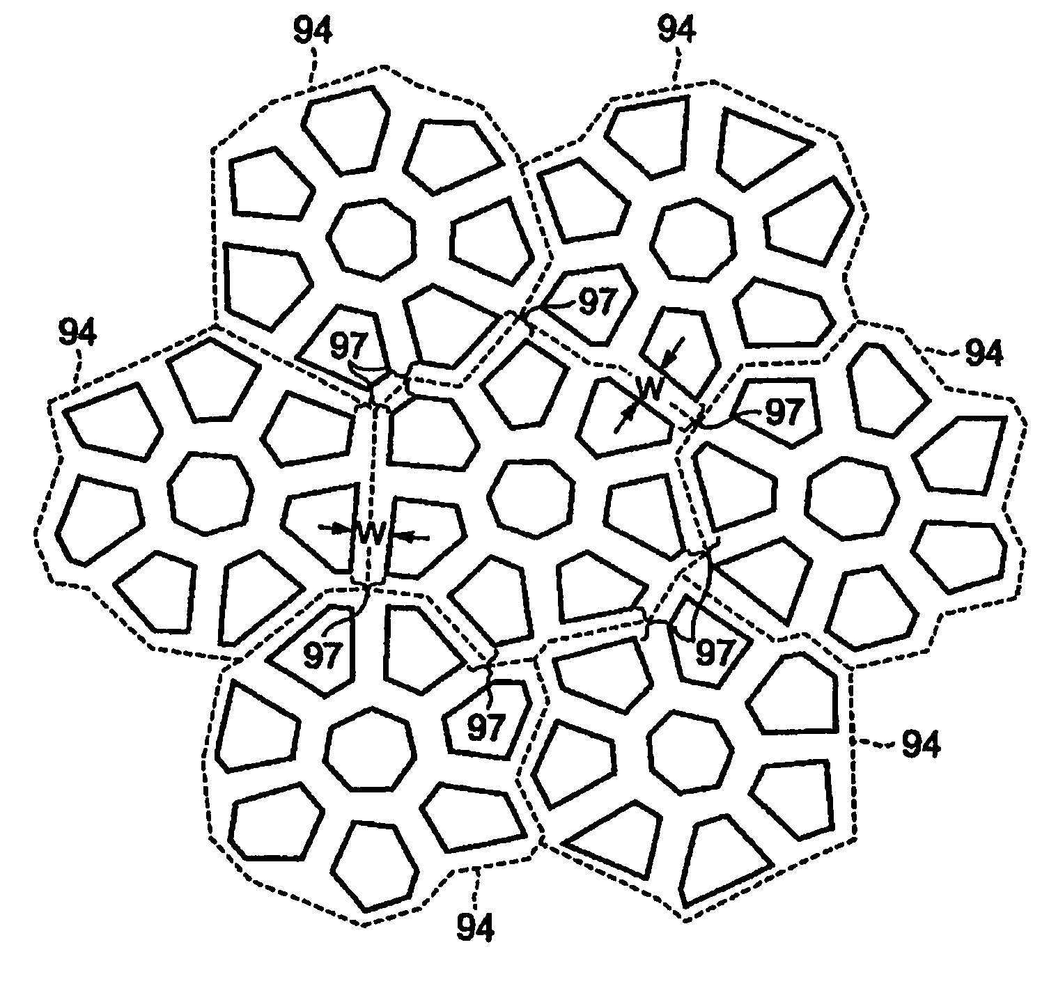
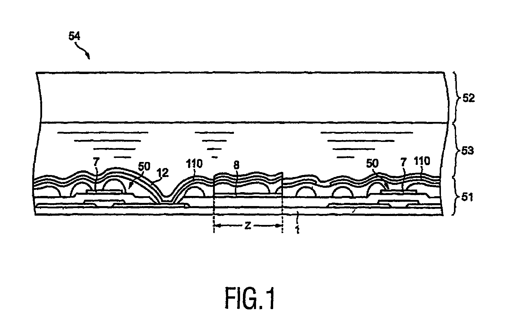
[0050]FIG. 1 is a partial cross-sectional view of the liquid crystal display device comprising a reflective electrode which has been formed using one example of a method of forming an reflector according to the present invention. In this embodiment, it will be described that a reflective electrode provided in a liquid crystal display device is formed using a method of forming a reflector according to the present invention, but it is noted that a reflective electrode provided in a device other than a liquid crystal display device can be formed using a method of forming a reflector according to the present invention.

[0051]The liquid crystal display device 54 comprises a TFT substrate assembly 51 (which is one example of the reflector structure according to the present invention) having a TFT 50, a reflective electrode (which is one example of the reflector according to the present invention) 110 and others. A...


PUM

PropertyMeasurementUnit
widthsaaaaaaaaaa
widthaaaaaaaaaa
diameteraaaaaaaaaa

Abstract

A method of forming a reflector member which contributes to an improvement of the quality of the image, and a reflective structure and a liquid crystal display device to which the method is applied. The plurality of holes are formed by exposing the first photosensitive film to light and developing it. A second photosensitive film is formed on the first photosensitive film in which the plurality of holes have been formed. The reflective electrode is formed on the second photosensitive film.

Description

BACKGROUND OF THE INVENTION[0001]1. Field of the Invention[0002]The invention relates to a method of forming a reflector member, to a reflective structure, and to liquid crystal display device.[0003]2. Description of Related Art[0004]In a liquid crystal display device comprising a reflective electrode or a reflector, such as a liquid crystal display device of reflective type, the reflective electrode or the reflector is often provided with recesses or projections in order to improve the quality of the image to be displayed. In order to provide the reflective electrode or the reflector with recesses or projections, photosensitive resin is applied and the applied photosensitive resin is patterned in a predetermined form before forming the reflective electrode or the reflector.[0005]It is possible to provide the reflective electrode or the reflector with recesses or projections by patterning the photosensitive resin in the predetermined form, but if the photosensitive resin is simply p...

Claims


Application Information

Patent Timeline
Patent Type & Authority Patents(United States)
IPC IPC(8): G02B5/08G02B5/02G02F1/1335G02B5/10
CPCG02F1/133553Y10S359/90G02F1/1335G02B5/10G02B5/02
Inventor SUMI, NAOKI
Owner TPO HONG KONG HLDG
Why Eureka
Try Eureka