Method and apparatus for resecting and replacing an aortic valve

a technology for aortic valves and resections, applied in the field of aortic valve resection and replacement methods, can solve the problems of low progress in the development of safer and less invasive valve delivery systems, high risk of morbidity and mortality, and substantial and invasive procedures for patients, so as to simplify the precise placement of devices and minimize the risks for patients.

Inactive Publication Date: 2009-06-09
MEDTRONIC INC
View PDF450 Cites 314 Cited by
  • Summary
  • Abstract
  • Description
  • Claims
  • Application Information

AI Technical Summary

Benefits of technology

[0023]Another object of the present invention is to allow the insertion of such a valve while minimizing the risks to the patient posed by large arterial incisions.
[0024]And another object of the present invention is to simplify the precise placement of such a valve.
[0026]Another object of the present invention is to allow the insertion of a device other than a valve, such as but not limited to a valve resection tool, a decalcifying tool, an aortic valve repair tool, or a stented aortic graft, while minimizing the risks to the patient posed by large arterial incisions.
[0027]And another object of the present invention is to simplify the precise placement of a device other than a valve, such as but not limited to a valve resection tool, a decalcifying tool, an aortic valve repair tool, or a stented aortic graft.

Problems solved by technology

Unfortunately, this procedure is a substantial and invasive undertaking for the patient.
While there have been significant advances in heart valve technology over the past 30 years, there has been little progress in the development of safer and less invasive valve delivery systems.
Given the current invasiveness of this procedure and the requirement to utilize cardiopulmonary bypass, aortic valve replacement surgery is associated with a high risk of morbidity and mortality.
Using the technology available at that time, success was limited: the valve area was increased only minimally, and nearly all patients had restenosis within one year.
However, these approaches still require cardiopulmonary bypass and cardiac arrest, which themselves entail significant morbidity and a prolonged post-operative recovery.
Unfortunately, although there has been great progress in the treatment of coronary artery disease without cardiopulmonary bypass (e.g., angioplasty, with or without stenting, and “off-pump” coronary artery bypass grafting), similar advances have not yet been realized in heart valve surgery.
The first challenge is to remove the diseased valve without causing stroke or other ischemic events that might result from the liberation of particulate material while removing the diseased valve.
The second challenge is to prevent cardiac failure during removal of the diseased valve.
However, as the diseased valve is removed, it becomes acutely and severely incompetent, causing the patient to develop heart failure which results in death unless the function of the valve is taken over by another means.
Therefore, any sizable incision made to the aorta in order to insert a standard valve prosthesis into the arterial system creates the potential for uncontrollable bleeding from the incision site.
Furthermore, even if bleeding is successfully controlled, pressures within the aorta may result in weakening of the aorta caused by aortic wall dissection.
In addition, large incisions on the aorta also increase the potential for liberating plaque from the aortic wall that can lead to embolic complications.
Unfortunately, however, none of these relatively flimsy valve prostheses have proven adequate to endure the repetitive stresses undergone by the aortic valve over the ten to twenty years typically required.
In addition to the foregoing, the precise placement of such expandable prosthetic valves in the correct sub-coronary position can be extremely challenging, particularly in view of the high pressure, pulsatile blood flow passing through the aorta.
Furthermore, expandable prosthetic valves would typically be positioned from a remote artery, which would reduce the ability to precisely control the placement and positioning of the device and therefore would increases the risk of obstructing the coronary arteries.

Method used


Image

  • Method and apparatus for resecting and replacing an aortic valve
  • Method and apparatus for resecting and replacing an aortic valve
  • Method and apparatus for resecting and replacing an aortic valve

Examples


Embodiment Construction

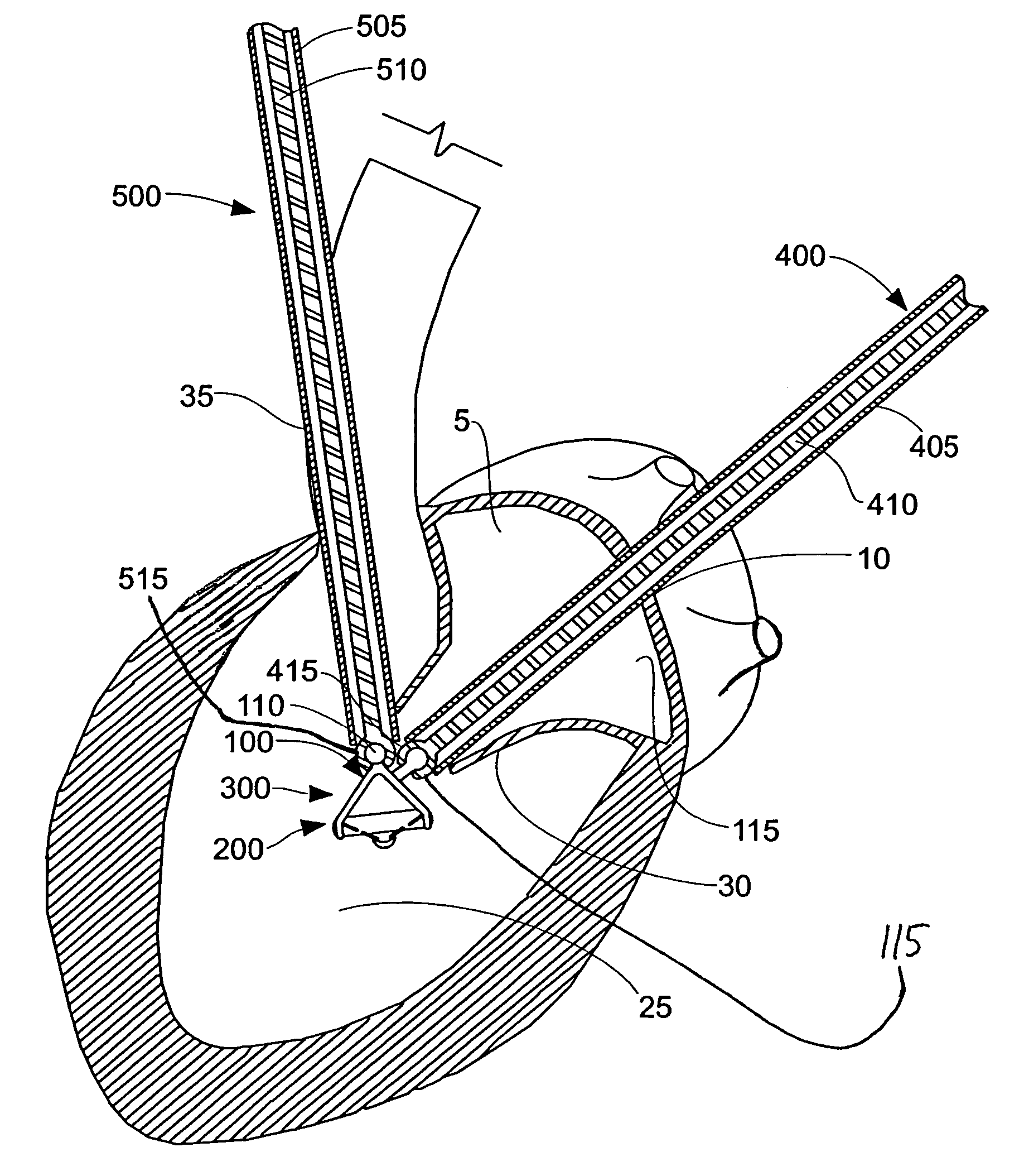
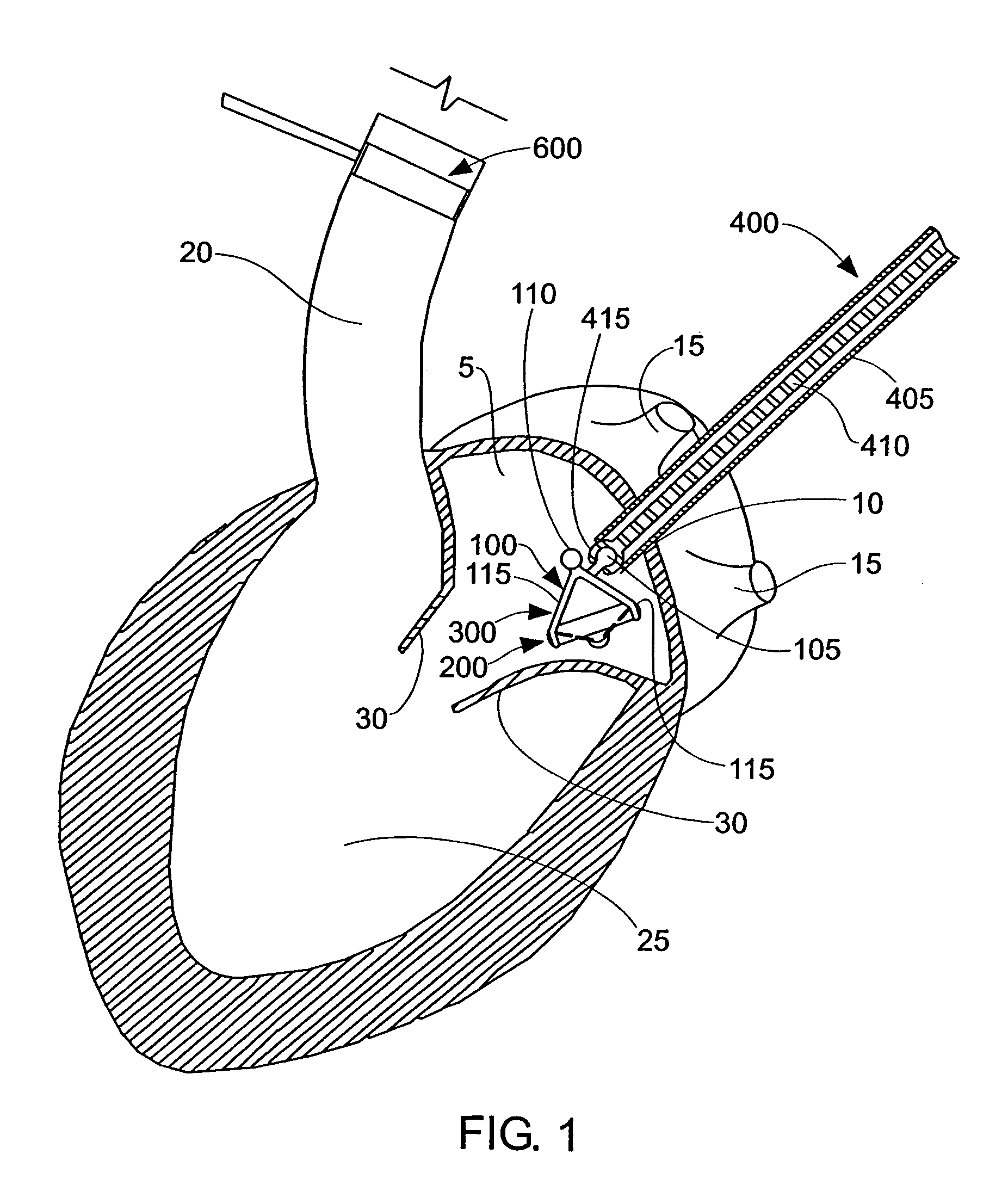
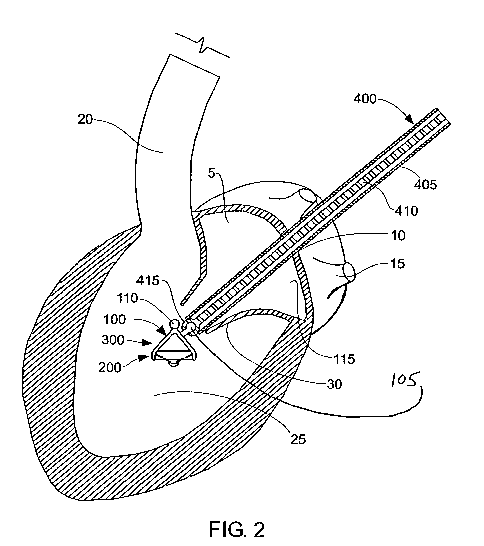
[0073]The present invention can be used to deliver or implant a variety of prostheses into the arterial system or left side of the heart. The prosthesis used in the preferred embodiment is an aortic valve prosthesis. Alternatively, the prosthesis may comprise, but is not limited to, a cylindrical arterial stent, an arterial prosthesis or graft, a ventricular assist device, a device for the treatment of heart failure such as an intraventricular counterpulsation balloon, chordae tendinae prostheses, arterial filters suitable for acute or chronic filtration of emboli from the blood stream, arterial occlusion devices and the like.

[0074]For clarity of illustration, the present invention will hereinafter be discussed in the context of implanting an aortic valve prosthesis.

[0075]It should also be appreciated that the present invention may be practiced either “on-pump” or “off-pump”. In other words, the present invention may be performed either with or without the support of cardiopulmonary...


PUM


Abstract

A method and apparatus for delivering a device to a given location within a heart, the method and apparatus being adapted for:passing a first catheter through the left atrium of the heart, through the mitral valve and into the left ventricle, and passing a second catheter through the aorta toward the heart, one or the other of the first catheter and the second catheter, with the device attached thereto, forming a device-carrying assembly for engagement with the remaining catheter;causing the device-carrying assembly and the remaining catheter to engage one another so as to form a connection therebetween; andretracting one of the device-carrying assembly and the remaining catheter in a direction opposite to the other of the device-carrying assembly and the remaining catheter so as to position the device relative to the given location within the heart.

Description

REFERENCE TO PRIOR PATENT APPLICATIONS[0001]This patent application:[0002](1) is a continuation-in-part of prior U.S. patent application Ser. No. 10 / 414,741, filed Apr. 16, 2003 now U.S. Pat. No. 7,201,761 by Steven B. Woolfson et al. for METHOD AND APPARATUS FOR RESECTING AND REPLACING AN AORTIC VALVE;[0003](2) is a continuation-in-part of prior U.S. patent application Ser. No. 09 / 896,259, filed Jun. 29, 2001 now U.S. Pat. No. 6,769,434 by John R. Liddicoat et al. for METHOD AND APPARATUS FOR PERFORMING A PROCEDURE ON A CARDIAC VALVE; and[0004](3) claims benefit of prior U.S. Provisional Patent Application Ser. No. 60 / 488,548, filed Jul. 18, 2003 by William E. Cohn for METHOD AND APPARATUS FOR RESECTING AND REPLACING AN AORTIC VALVE.[0005]The three above-identified patent applications are hereby incorporated by reference.FIELD OF THE INVENTION[0006]This invention relates to apparatus and methods for performing cardiac surgery in general, and more particularly to apparatus and metho...

Claims


Application Information

Patent Timeline
Patent Type & Authority Patents(United States)
IPC IPC(8): A61F2/24A61F11/00A61M29/00A61B17/32
CPCA61F2/2427
Inventor COHN, WILLIAM E.
Owner MEDTRONIC INC
Why Eureka
Try Eureka