High resolution gamma measurements and imaging

a technology of gamma radiation and high resolution, applied in the direction of radiation intensity measurement, x/gamma/cosmic radiation measurement, instruments, etc., can solve the problems of less spatial resolution and less accurate knowledge of formation bedding planes

Active Publication Date: 2009-06-09
BAKER HUGHES INC
View PDF8 Cites 8 Cited by
  • Summary
  • Abstract
  • Description
  • Claims
  • Application Information

AI Technical Summary

Problems solved by technology

Cylindrically shaped gamma radiation detectors will have less spatial resolution and therefore will result in less accurate knowledge of the formation bedding planes.

Method used


Image

  • High resolution gamma measurements and imaging
  • High resolution gamma measurements and imaging
  • High resolution gamma measurements and imaging

Examples


Embodiment Construction

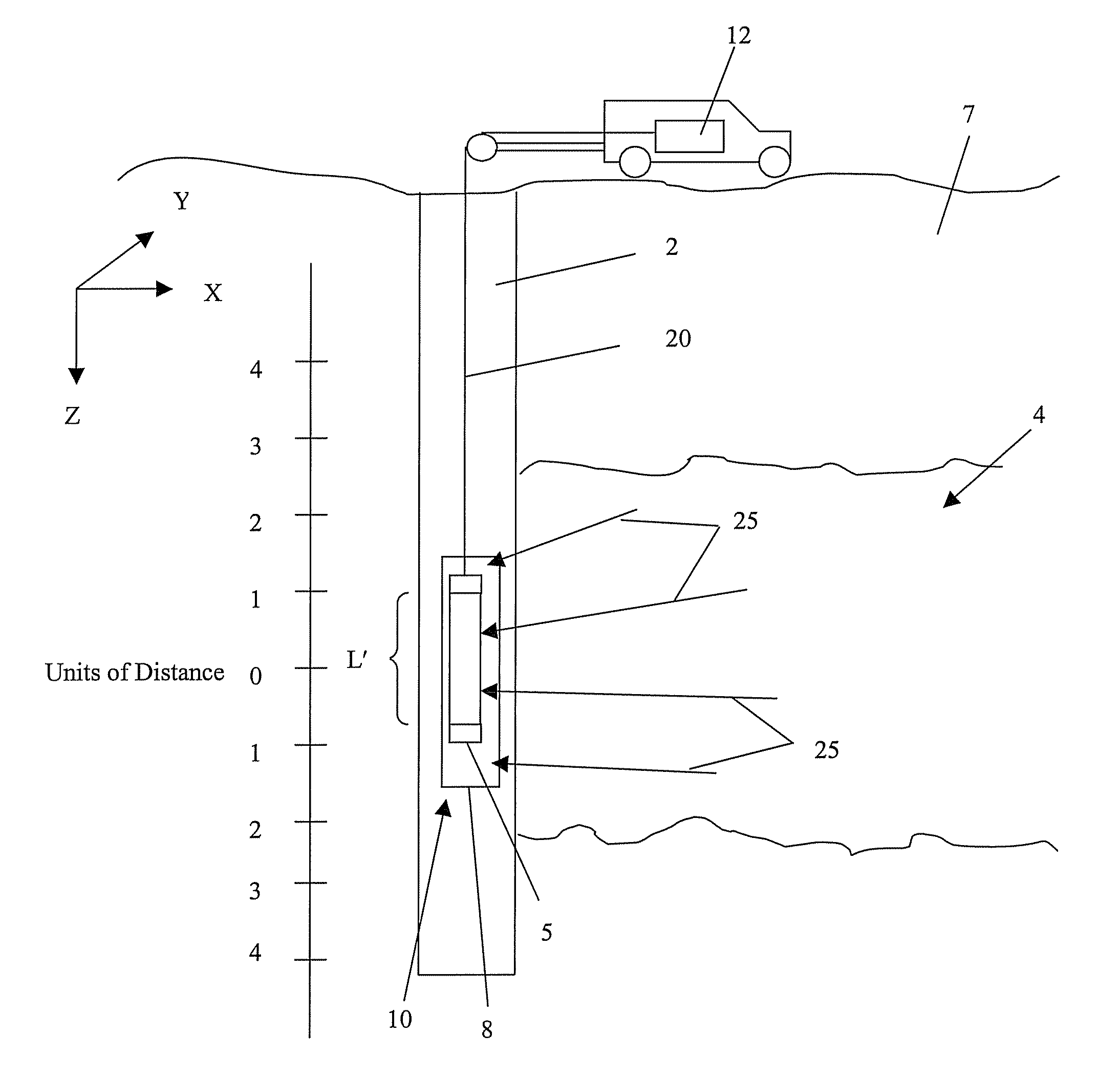
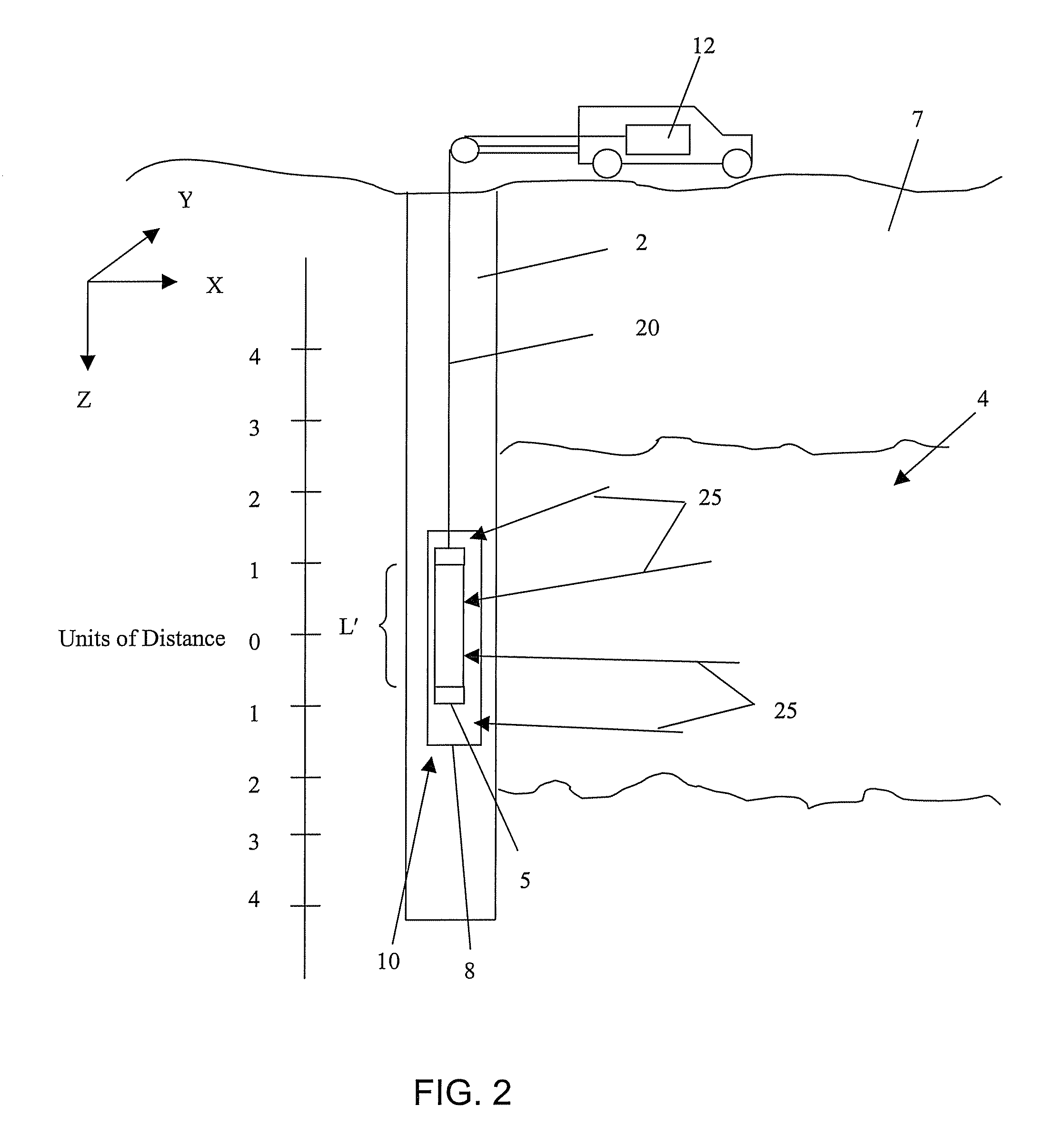
[0025]The teachings provide techniques for malting measurements of gamma radiation emitted from a formation. The measurements are performed in a borehole and provide improved spatial resolution. In general, the measurements are performed using a scintillator and at least two photodetectors. Generally, each photodetector is disposed on a side of the scintillator. A gamma ray (or gamma particle) that interacts within the scintillator will generate a photon that can propagate to one of the photodetectors and be detected. The photodetector will provide an output signal related to the number and energy of photons detected. The location where the gamma ray interacted in the scintillator can be determined by knowing information such as the attenuation constant of the scintillator and measuring the output signal of each photodetector. Determining the location provides the improved spatial resolution.

[0026]Referring to FIG. 1, an exemplary embodiment of a well logging instrument 10 is shown ...


PUM


Abstract

A method for measuring radiation in a borehole, the method including placing a detector comprising a scintillator and a plurality of photodetectors in the borehole; detecting a radiation interaction with a first photodetector; detecting the radiation interaction with at least a second photodetector; and determining a location of the interaction from the detecting; wherein the location provides information regarding formations surrounding the borehole.

Description

BACKGROUND OF THE INVENTION[0001]1. Field of the Invention[0002]This invention relates to measuring gamma radiation emitted from a subsurface formation. In particular, the measuring is performed within a borehole.[0003]2. Description of the Related Art[0004]A variety of geologic formations contain reservoirs of oil and gas. Measuring properties of the geologic formations provides information that can be useful for locating the reservoirs of oil and gas. Typically, the oil and gas are accessed by drilling boreholes into the subsurface of the earth. The boreholes also provide access to take measurements of the geologic formations.[0005]Well logging is a technique used to take measurements of properties of the geologic formations from the boreholes. In one embodiment, a logging instrument is disposed in a drill string in proximity to a drill bit. The logging instrument is used to take the measurements and send data via telemetry to the surface for recording. This type of well logging i...

Claims


Application Information

Patent Timeline
Patent Type & Authority Patents(United States)
IPC IPC(8): G01V1/00
CPCG01V5/06
Inventor HASSAN, GAMAL A.MADIGAN, WILLIAMLINDSAY, GAVINKURKOSKI, PHIL L.
Owner BAKER HUGHES INC
Why Eureka
Try Eureka