
Thermal detector for electromagnetic radiation and infrared detection device using such detectors

a detector and electromagnetic radiation technology, applied in the field of thermal detectors, can solve the problems of reducing the width and/or thickness of the arms, affecting the detection effect, and the system of arms has a deleterious effect, so as to prevent the detection of electromagnetic radiation and achieve the effect of thermal coupling with the substra

Inactive Publication Date: 2009-06-09
COMMISSARIAT A LENERGIE ATOMIQUE ET AUX ENERGIES ALTERNATIVES
View PDF4 Cites 3 Cited by
  • Summary
  • Abstract
  • Description
  • Claims
  • Application Information

AI Technical Summary

Benefits of technology

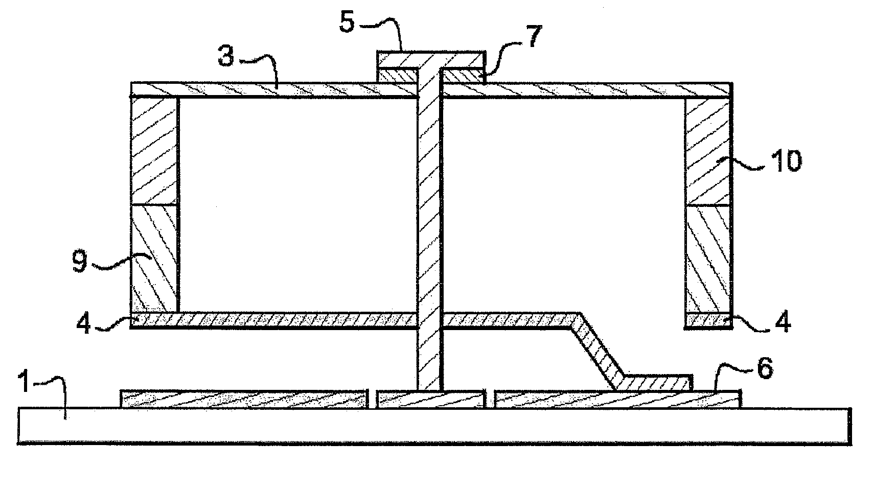
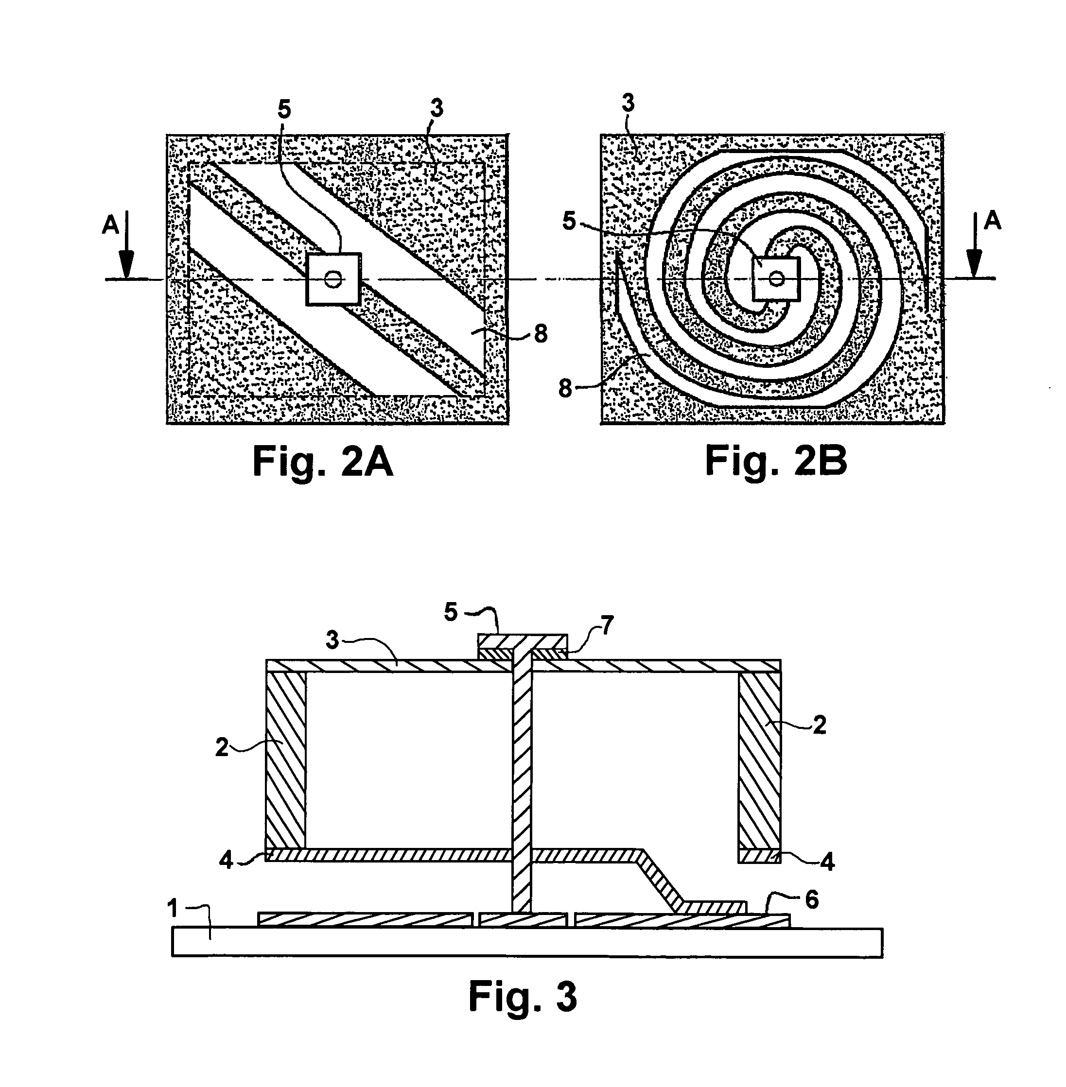
[0042]As a result, the electric current in the bolometric material flows exclusively at right angles to the surface of the support. This way, almost the entire surface is freed up, thereby malting it possible to optimize optical absorption and thermal isolation. What is more, this configuration, which is highly suitable for achieving reduced pitch spacing, makes it possible to produce thermal isolation arms at two different levels, thus providing an additional degree of freedom when designing the detector. The fill factor thus obtained is ideal from the point of view of absorption of infrared radiation. This approach is also very favorable in terms of thermal mass because all the thermometric material is active thanks to the contact established on the sheet of this material. What is more, the thermometric material is absent from almost the entire surface of the cavity which then becomes a true Fabry-Perrot cavity which can be adjusted to exactly one quarter of the wavelength to be detected, thus enhancing detection performance in a known way.
[0043]Such a layout therefore males it possible to improve the thermal isolation properties of the bolometer without adversely affecting the stability of the micro-bridges. In addition, the proposed solution results in an ideal fill factor.
[0051]Thus, this solution involves eliminating any physical continuity of the electrical conductor in the retention and thermal isolation devices of the thermal material, especially bolometric material, and obtaining an electrical connection between the detector and the readout circuit by capacitive coupling.
[0052]In such a device, thermal losses due to conduction by the electrical conductor are eliminated completely. At the same time, the stability of the micro-bridges and the fill factor of the detector are not affected and biasing of the detector is facilitated.
[0059]Such a device also advantageously comprises a reference or compensation thermal detector which is also referred to as a “baseline resistor” in the context of bolometers. The latter does not have the ability to detect electromagnetic radiation but is otherwise identical to the active thermal detector in every respect. In practice, this is achieved by using a metallic post having a top which entirely covers the surface of the absorber as a fixing means, thus preventing any detection of electromagnetic radiation and also ensuring effective thermal coupling with the substrate.

Problems solved by technology

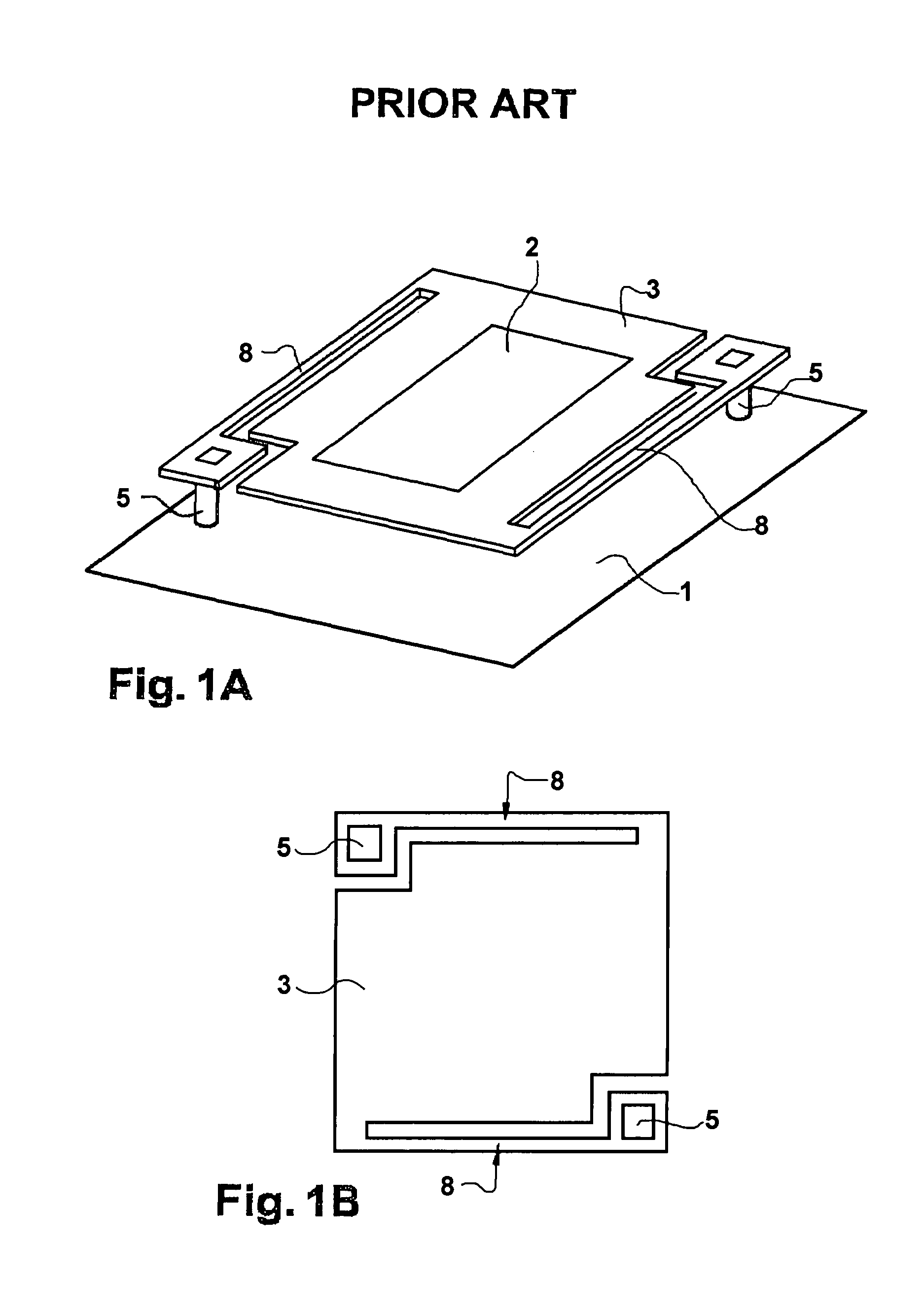
When implemented in the plane of the bolometric plate, this system of arms has a deleterious effect in terms of the fill factor of the pixel or elementary detector.
Experience shows that it is not possible to significantly increase the length of arms (8) or reduce their width and / or thickness without affecting the rigidity of the structure.
In fact, these elements are a mechanical weak point which affects the stability of the micro-bridges which may pivot or deform and therefore come into contact with the substrate, thus adversely affecting thermal isolation and consequently significantly impairing the performance of the detector.
Reducing the width and / or thickness of these elements results in increased electrical resistance when accessing the detector and, if this resistance is too high, this adversely affects optimal biasing of the detector.
The presence of this layer in the thermal isolation devices can therefore significantly degrade their thermal isolation and consequently degrade the performance of the detector.

Method used


Image

  • Thermal detector for electromagnetic radiation and infrared detection device using such detectors
  • Thermal detector for electromagnetic radiation and infrared detection device using such detectors
  • Thermal detector for electromagnetic radiation and infrared detection device using such detectors

Examples


Embodiment Construction

[0070]The invention therefore relates to an elementary thermal detector and, more especially, the layout of the sensitive material of this detector which is its distinctive feature compared with a bolometer according to the prior art, as shown in FIG. 1.

[0071]An active detector which uses a resistive bolometer according to the invention is described in greater detail, reference being made to FIGS. 2 and 3.

[0072]Such a bolometer is produced on a substrate (1) which incorporates an integrated readout circuit. On this substrate there is a metallic layer (6) which is used both to reflect incident infrared radiation and to electrically connect the bolometer.

[0073]On this metallic layer (6) which is applied using conventional photolithographic methods, a first sacrificial layer of 0.2 μm to 0.5 μm is temporarily used as a support for conductive film (4) (extremely thin in order to limit thermal losses) which, once defined, ensures a lower contact or a lower electrode of the thermometer. A...


PUM


Abstract

A thermal detector comprising a sensitive material having at least one electrical property of which varies with temperature; an electromagnetic radiation absorber which is in contact with the sensitive material; a substrate providing the function of support; and electrically conductive elements providing electrical continuity between sensitive material and substrate. The sensitive material is wholly or partly in the form of a sheet extending in a direction which is essentially perpendicular to the plane of the substrate. The sensitive material is suspended above the substrate by the absorber which is fixed to the sensitive material in the upper region of the sheet. The absorber is suspended by fixing means which is mechanically connected to the substrate.

Description

FIELD OF THE INVENTION[0001]The present invention relates to a thermal detector, especially a bolometric detector, as well as to an infrared detection device which uses such detectors.[0002]The application area of the invention is infrared imaging in particular.BACKGROUND OF THE INVENTION[0003]By definition, a thermal detector is used to measure the amount of incident radiant flux, for example the power of electromagnetic radiation in the infrared ray region.[0004]As far as infrared detectors are concerned, devices designed in the form of an array which are capable of operating at ambient temperature, i.e. which do not require cooling, are known—these are contrasted with detection devices referred to as “quantum” detectors which can only operate at extremely low temperature, typically at the temperature of liquid nitrogen.[0005]These detectors generally comprise a sensing element which can be warmed by infrared radiation which is characteristic of the temperature and emissivity of o...

Claims


Application Information

Patent Timeline
Patent Type & Authority Patents(United States)
IPC IPC(8): H01L27/14G01J5/00
CPCG01J5/20
Inventor OUVRIER-BUFFET, JEAN-LOUISARNAUD, AGNESBISOTTO, SYLVETTEPEREZ, ANDRE
Owner COMMISSARIAT A LENERGIE ATOMIQUE ET AUX ENERGIES ALTERNATIVES
Learn More