Apparatus and method for predicting battery capacity and fitness for service from a battery dynamic parameter and a recovery voltage differential

a dynamic parameter and recovery voltage differential technology, applied in the field of electromechanical battery testers, can solve the problems of inadequate battery and string conditions determined solely on the basis of battery conductance measurements

Active Publication Date: 2009-06-09
MIDTRONICS
View PDF437 Cites 85 Cited by
  • Summary
  • Abstract
  • Description
  • Claims
  • Application Information

AI Technical Summary

Problems solved by technology

However, in certain applications, such as golf cars that are powered over an extended period of time by battery strings, determining battery and string conditions solely on the basis of battery conductance measurements may provide inadequate results.

Method used


Image

  • Apparatus and method for predicting battery capacity and fitness for service from a battery dynamic parameter and a recovery voltage differential
  • Apparatus and method for predicting battery capacity and fitness for service from a battery dynamic parameter and a recovery voltage differential
  • Apparatus and method for predicting battery capacity and fitness for service from a battery dynamic parameter and a recovery voltage differential

Examples


Embodiment Construction

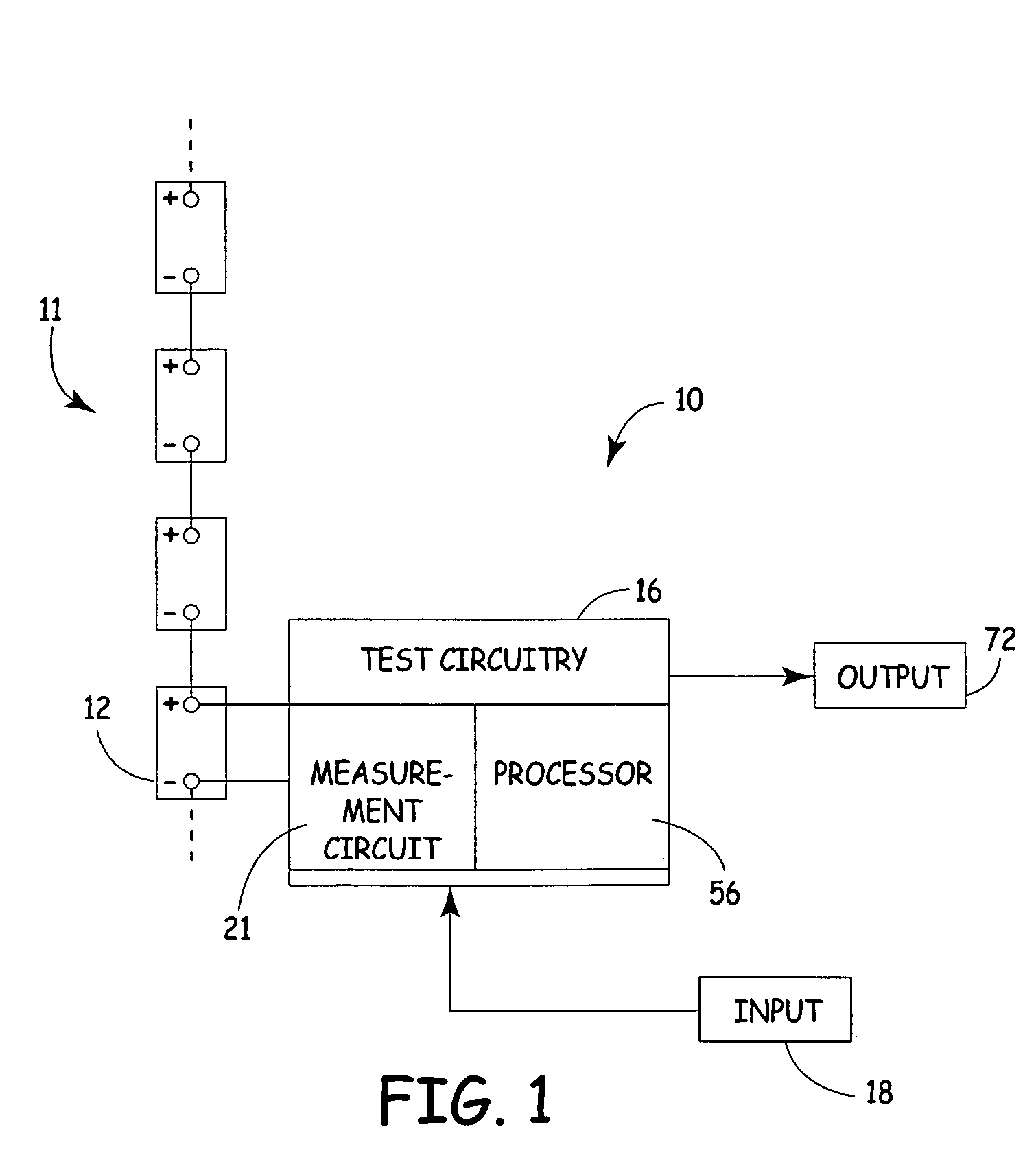
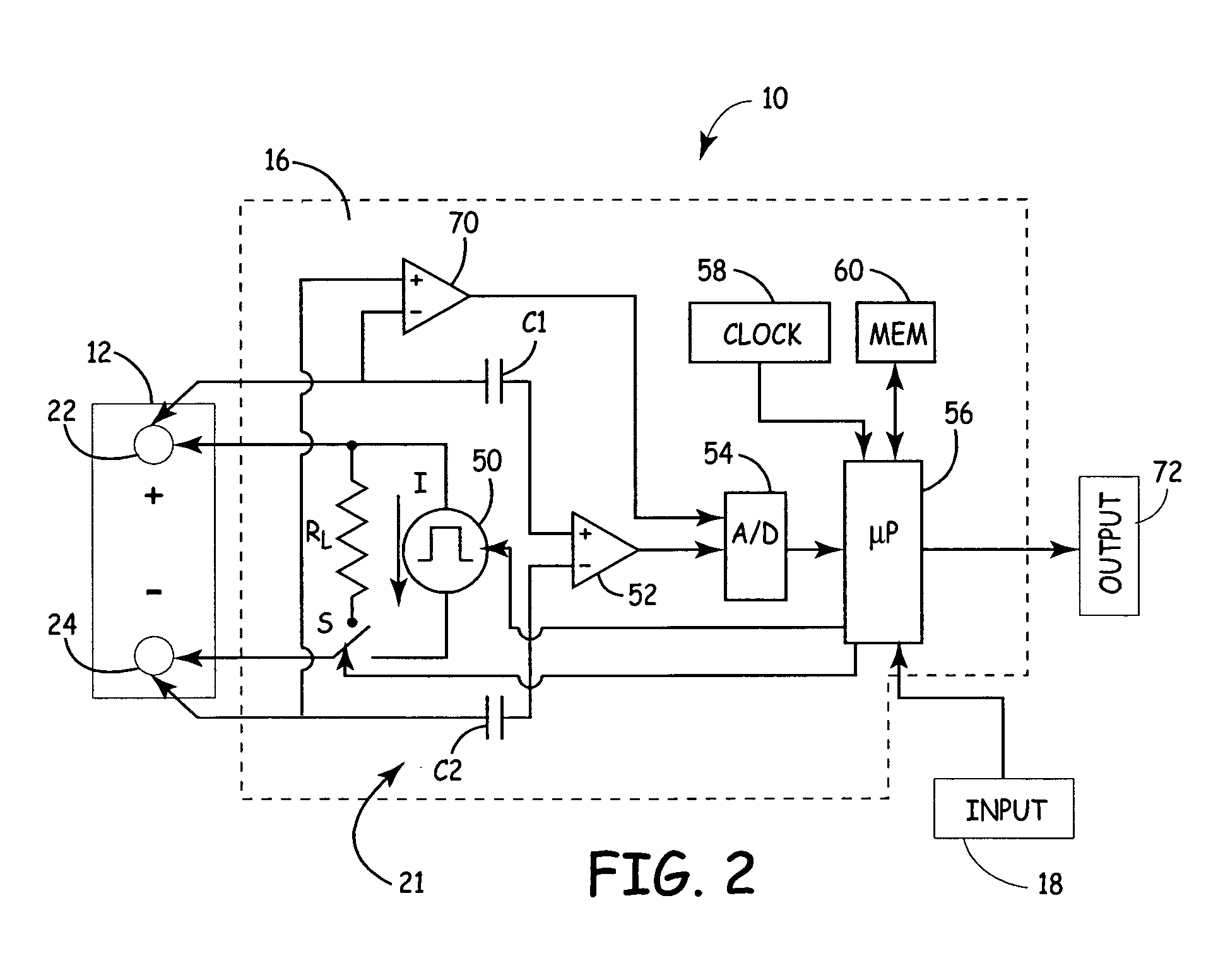
[0009]FIG. 1 is a very simplified block diagram of a battery tester 10 in accordance with an illustrative embodiment of the present invention. The same reference numerals are used in the various figures to represent the same or similar elements. Battery tester 10 includes test circuitry 16 that electrically couples to a battery 12 of a battery string 11. Test circuitry 16 includes measurement circuit 21 and processor 56. Measurement circuit 21, which operates under the control of processor 56, can be any circuit configuration which is capable of carrying out different battery voltage measurements, current measurements, etc., required to determine battery capacity in accordance with the present invention.

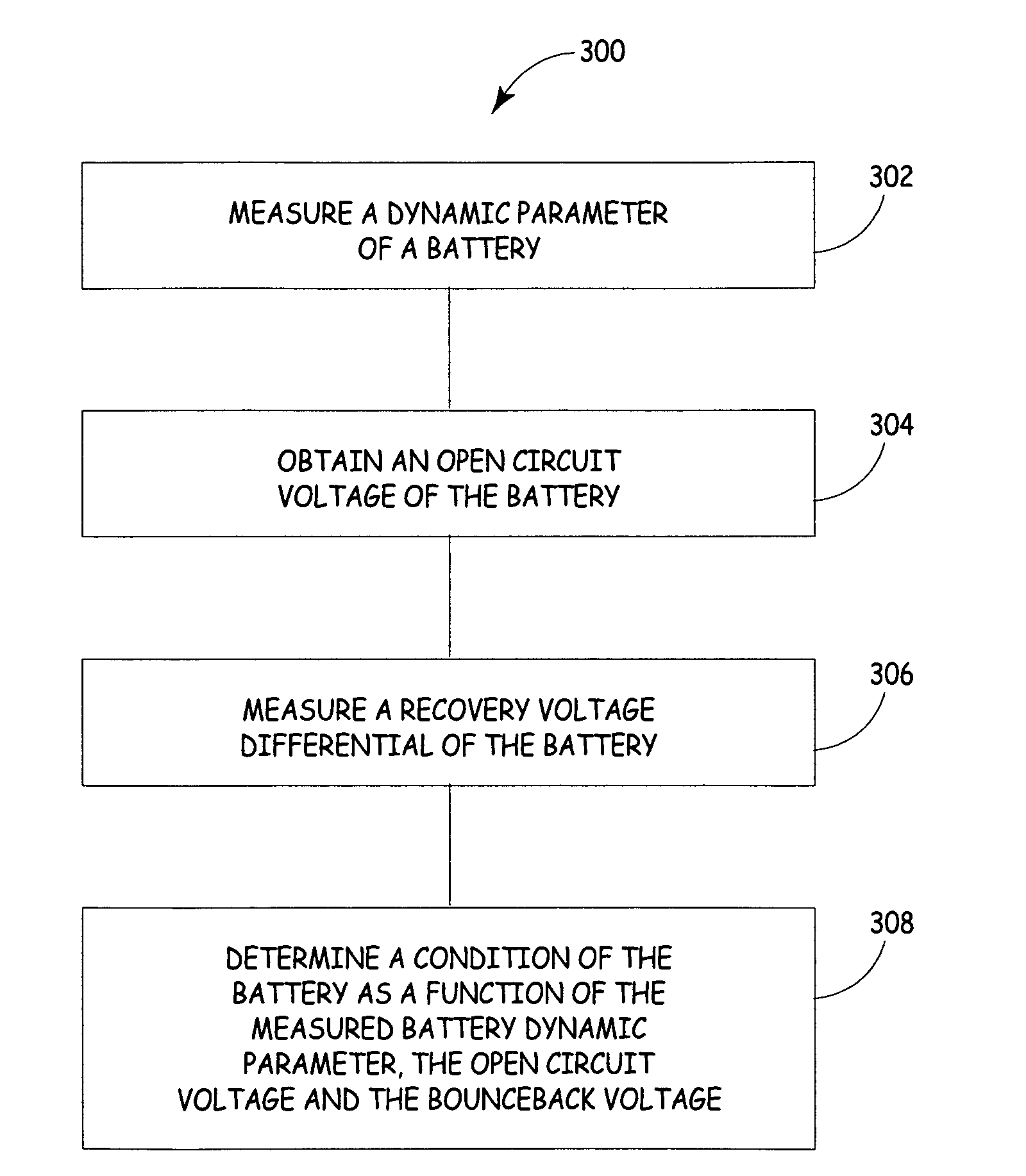
[0010]In accordance with the present invention, battery tester 10 combines prediction of battery capacity from a battery dynamic parameter, such as battery conductance, along with an additional judgment based on a recovery voltage differential. As used herein, the recovery voltage di...


PUM

PropertyMeasurementUnit
of timeaaaaaaaaaa
of timeaaaaaaaaaa
period of timeaaaaaaaaaa

Abstract

A method and apparatus for testing a storage battery is provided in which a battery is measured to obtain a battery dynamic parameter value such as conductance. The battery is measured to obtain an open circuit voltage, a resistance and a recovery voltage differential. A condition of the battery is determined as a function of the measured battery dynamic parameter, the open circuit voltage and the recovery voltage differential.

Description

BACKGROUND OF THE INVENTION[0001]The present invention relates to testing of storage batteries, and in particular storage batteries typically used in electric vehicles such as golf cars. More specifically, the present invention relates to electronic battery testers that measure a dynamic parameter of a battery and determine its capacity and fitness for further service.[0002]Electronic battery testers are used to test storage batteries. Various examples of such testers are described in U.S. Pat. No. 3,873,911, issued Mar. 25, 1975, to Champlin, entitled ELECTRONIC BATTERY TESTING DEVICE; U.S. Pat. No. 3,909,708, issued Sep. 30, 1975, to Champlin, entitled ELECTRONIC BATTERY TESTING DEVICE; U.S. Pat. No. 4,816,768, issued Mar. 28, 1989, to Champlin, entitled ELECTRONIC BATTERY TESTING DEVICE; U.S. Pat. No. 4,825,170, issued Apr. 25, 1989, to Champlin, entitled ELECTRONIC BATTERY TESTING DEVICE WITH AUTOMATIC VOLTAGE SCALING; U.S. Pat. No. 4,881,038, issued Nov. 14, 1989, to Champlin, ...

Claims


Application Information

Patent Timeline
Patent Type & Authority Patents(United States)
IPC IPC(8): G01N27/416
CPCG01R31/3662G01R31/389
Inventor KLANG, JAMES K.JEZIORCZAK, KRZYSZTOF
Owner MIDTRONICS
Why Eureka
Try Eureka