Computer housing shock absorber device for a vibration source frame

a shock absorber device and computer housing technology, applied in the direction of instruments, liquid fuel engines, electrical apparatus casings/cabinets/drawers, etc., can solve the problems of only being able to provide complete shock absorption effectiveness for the entire host computer housing, rubber shock absorber cushion material is unable to provide complete shock absorption effectiveness, etc., to prevent internal components and connecting parts from falling off, the effect of reducing the vibration force on the entire computer housing

Active Publication Date: 2009-06-09
SUPER MICRO COMP
View PDF28 Cites 36 Cited by
  • Summary
  • Abstract
  • Description
  • Claims
  • Application Information

AI Technical Summary

Benefits of technology

[0006]A primary objective of the present invention is to provide a computer housing shock absorber device for a vibration source frame that uses shock absorber elements equally connected to connecting interfaces between an outer fixing frame fixedly disposed with heat dissipating fans and an inner fixing frame and a U-shaped holding space of a computer housing. The vibratory moment produced when the heat dissipating fans are rotating is transmitted outward through the outer fixing frame and absorbed by a plurality of the shock absorber elements, thus, the vibratory force on the entire computer housing is substantially reduced, noise is decreased, moreover, the shock absorber elements effectively prevent the risk of internal components and connecting pieces of the computer housing from coming loose due to vibration.

Problems solved by technology

However, such devices are only applicable for use in small spaces, for example, the interior space of a power supply, whereas a large scale server or host computer housing, wherein the interior space is relatively large, has a great number of heat dissipating fans and a great number of internal frames.
However, the rubber shock absorbing cushion material is unable to provide complete shock absorption effectiveness for the entire host computer housing.

Method used


Image

  • Computer housing shock absorber device for a vibration source frame
  • Computer housing shock absorber device for a vibration source frame
  • Computer housing shock absorber device for a vibration source frame

Examples


Embodiment Construction

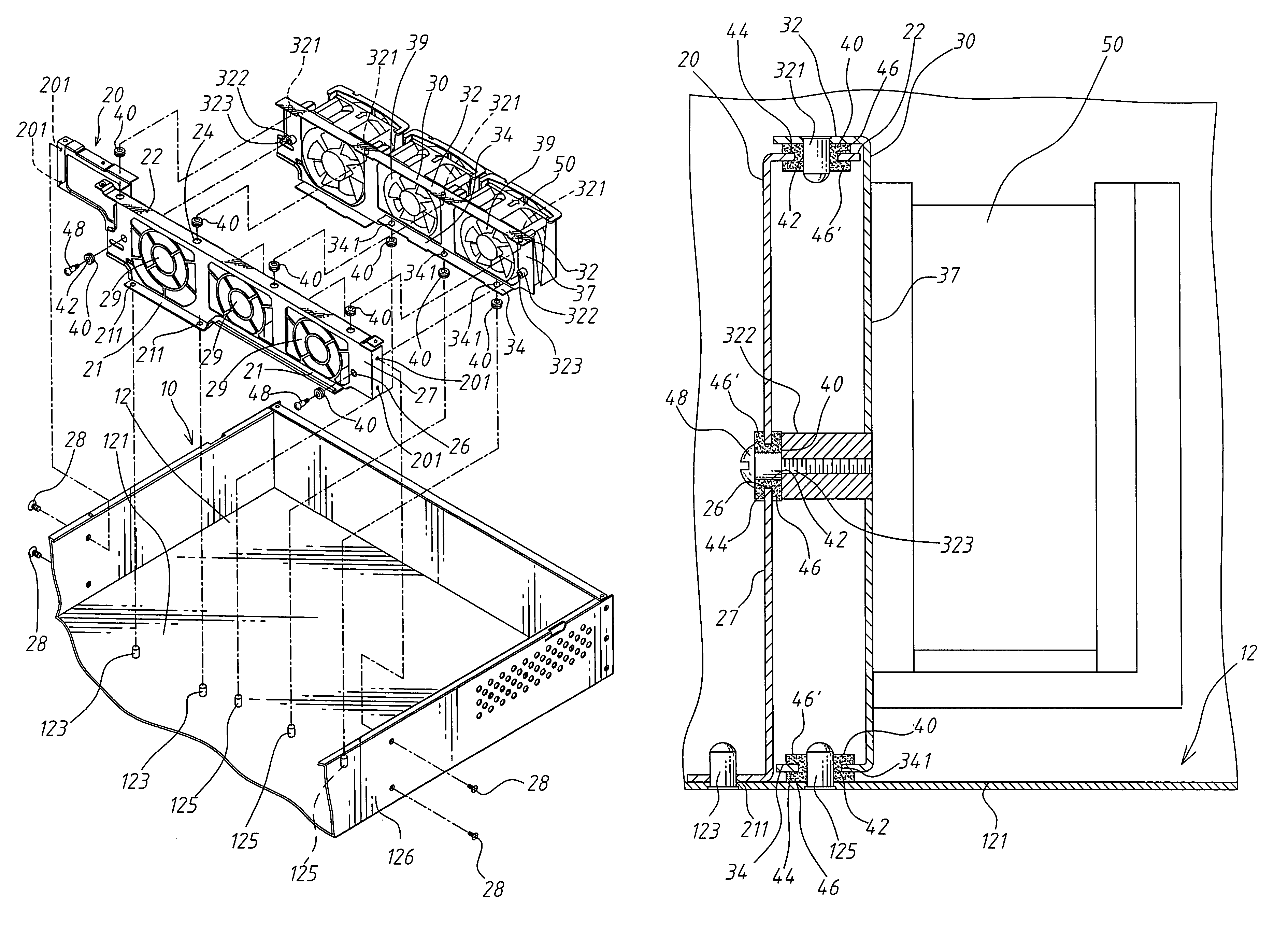
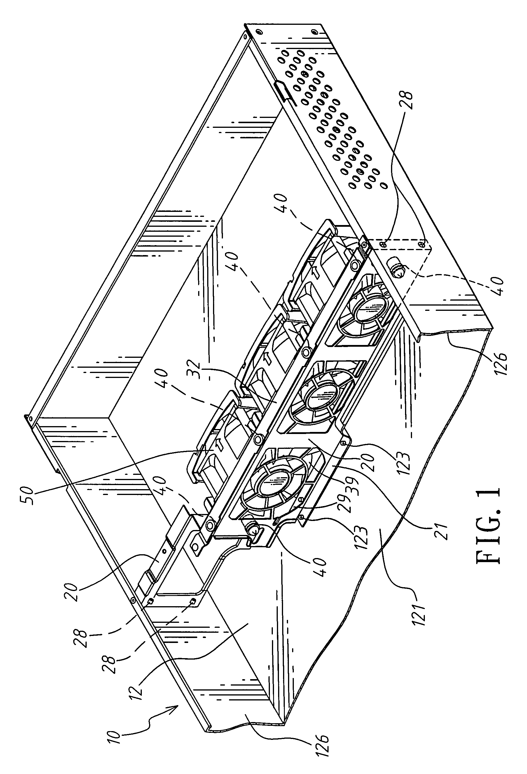
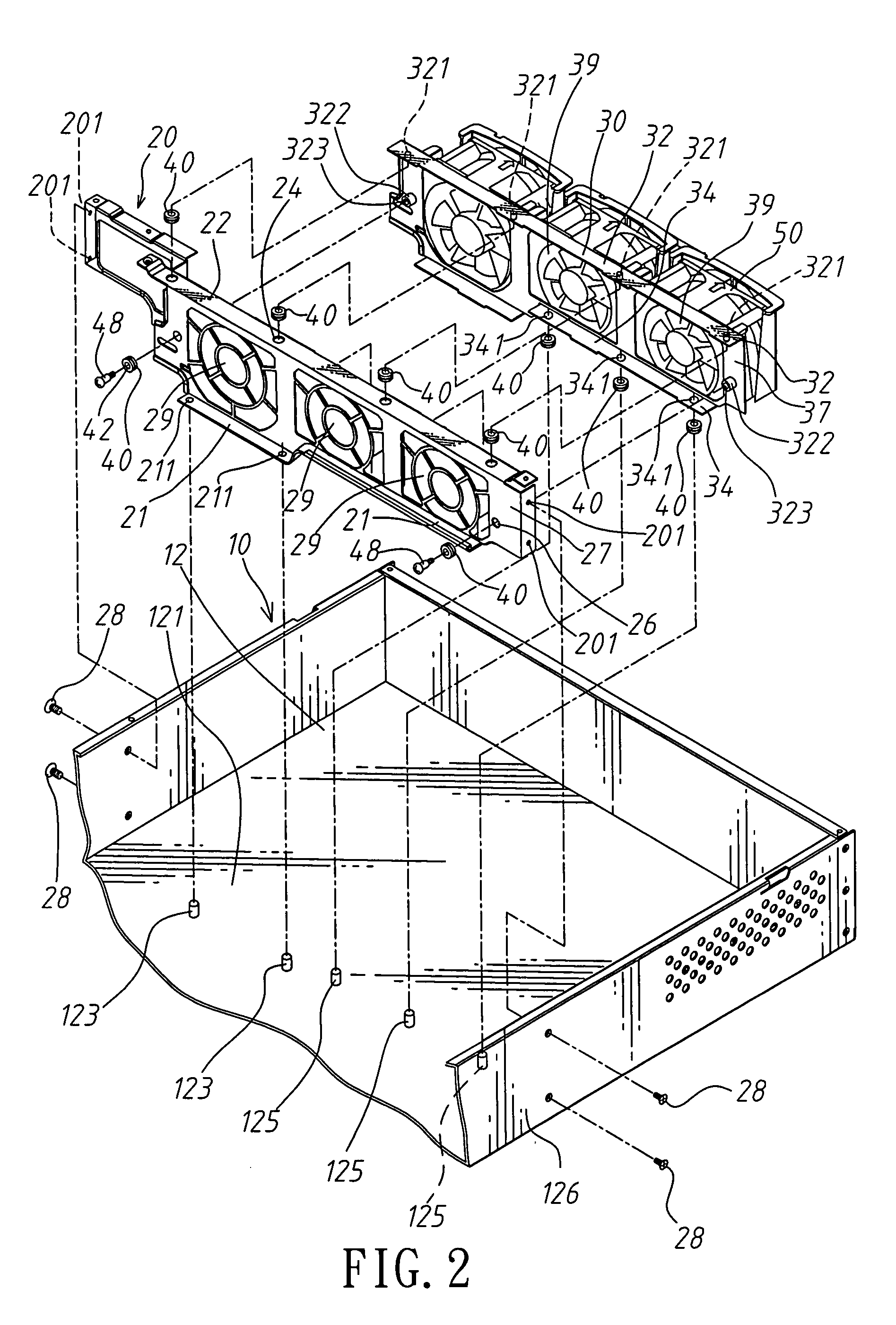
[0016]Referring to FIGS. 1, 2, 3, and 4, which show the computer housing shock absorber device for a vibration source frame provided by the present invention, comprising:

[0017]A computer housing 10 provided with a U-shaped holding space 12.

[0018]An inner fixing frame 20, transversally fixed within the U-shaped holding space 12, at least more than one connecting hole 24 is defined in a horizontal upper surface 22 of the inner fixing frame 20.

[0019]An outer fixing frame 30, on outer sides of which are fixedly clamped at least more than one heat dissipating fan 50. A top portion of the outer fixing frame 30 is configured with a horizontal upper surface 32, and connecting posts 321 are evenly disposed on a bottom surface of the horizontal upper surface 32.

[0020]At least more than one shock absorber element 40 (as depicted in FIG. 8), formed as cylindrical bodies, in the center of each of which is defined a through hole 42. A recessed circular groove 44 is defined in the circumference of...


PUM


Abstract

A computer housing shock absorber device for a vibration source frame, which includes:a computer housing provided with a U-shaped holding space;an inner fixing frame fixed within the U-shaped holding space;an outer fixing frame;The shock absorber elements mounted on circumferential edge walls of the connecting holes of the inner fixing frame. Upper and lower portions of each of the recessed circular grooves of the shock absorber elements are respectively provided with a cylindrical body, and one of the cylindrical bodies of each of the shock absorber elements lies between the upper surface of the outer fixing frame and the upper surface of the inner fixing frame. Accordingly, the vibratory moment on the outer fixing frame produced by rotation of the fans is absorbed by the shock absorber elements.

Description

BACKGROUND OF THE INVENTION[0001](a) Field of the Invention[0002]The present invention provides a computer housing shock absorber device for a vibration source frame, and more particularly to a device that uses shock absorber elements to respectively absorb the torsional moment and vibratory force imparted on a frame body by fan motors to achieve shock absorption effectiveness of the entire computer housing.[0003](b) Description of the Prior Art[0004]At least more than one fan is installed within a conventional server or host computer, and a typical structure, such as U.S. patent application Ser. No. 11 / 320,840, is provided with rubber cushions (30) and cylindrical bodies (40) to serve as connecting elements to achieve shock absorption effectiveness. However, such devices are only applicable for use in small spaces, for example, the interior space of a power supply, whereas a large scale server or host computer housing, wherein the interior space is relatively large, has a great num...

Claims


Application Information

Patent Timeline
Patent Type & Authority Patents(United States)
IPC IPC(8): H05K7/20F04D29/66
CPCH05K7/20727
Inventor CHEN, RICHARD
Owner SUPER MICRO COMP
Why Eureka
Try Eureka