In-flight verification of instrument landing system signals

a technology of in-flight verification and instrument landing system, which is applied in the direction of instruments, navigation instruments, process and machine control, etc., can solve the problems of pilots being misinformed as to the position in space of aircraft relative to runway, difficulty or impossible for pilots to rely on visual observation of landing site to safely land, and transmission anomalies affecting signals post-transmission that are generally not discernable from the ground

Active Publication Date: 2009-06-09
MARCUM FR
View PDF4 Cites 47 Cited by
  • Summary
  • Abstract
  • Description
  • Claims
  • Application Information

AI Technical Summary

Benefits of technology

[0015]In accordance with an embodiment of the invention, a system, to enable in-flight verification of an instrument landing system (ILS) transmission, may include the following. A first unit, responsive to in-flight reception of an ILS transmission, is arranged to provide a first output indicative of a point in space representative of a predetermined feature of an ILS approach to a runway. A second unit, responsive to received positional data (e.g., GPS data), is arranged to provide a second output representative of the actual location in space of the point in space indicated by the first output. A database access facility is arranged to enable access to at least one database to provide a data output representing data usable to determine an intended spatial characteristic of the ILS feature (e.g., the intended location of the same point in space or the glide path angle) consistent with accurate ILS operation (e.g., access geographical runway location data, ILS specification data, etc.). A third unit, responsive to the first, second and data outputs and arranged to provide a discrepancy output representative of a discrepancy between the intended spatial characteristic and that actual location in space.

Problems solved by technology

Reduced visibility, due to adverse weather conditions, may make it difficult or impossible for a pilot to rely upon visual observation of the landing site to safely land an aircraft.
However, if the ILS signal which the pilot would rely upon is, in fact, not available at its intended position in space, any error in that position may cause the pilot to be misinformed as to the position in space of the aircraft relative to the runway.
However, transmission anomalies affecting signals post transmission are generally not discernable from the ground.
In fact, changing atmospheric or ground conditions, as well as other conditions such as temporary standing of a large aircraft in the field of an ILS antenna, may affect ILS signal integrity at any time and for any duration of time.
As a result, in the absence of truly current information a pilot may be faced with a choice of landing with reliance on ILS signals which he is not aware are providing inaccurate indications, or redirecting the landing to a different airport.

Method used


Image

  • In-flight verification of instrument landing system signals
  • In-flight verification of instrument landing system signals
  • In-flight verification of instrument landing system signals

Examples


Embodiment Construction

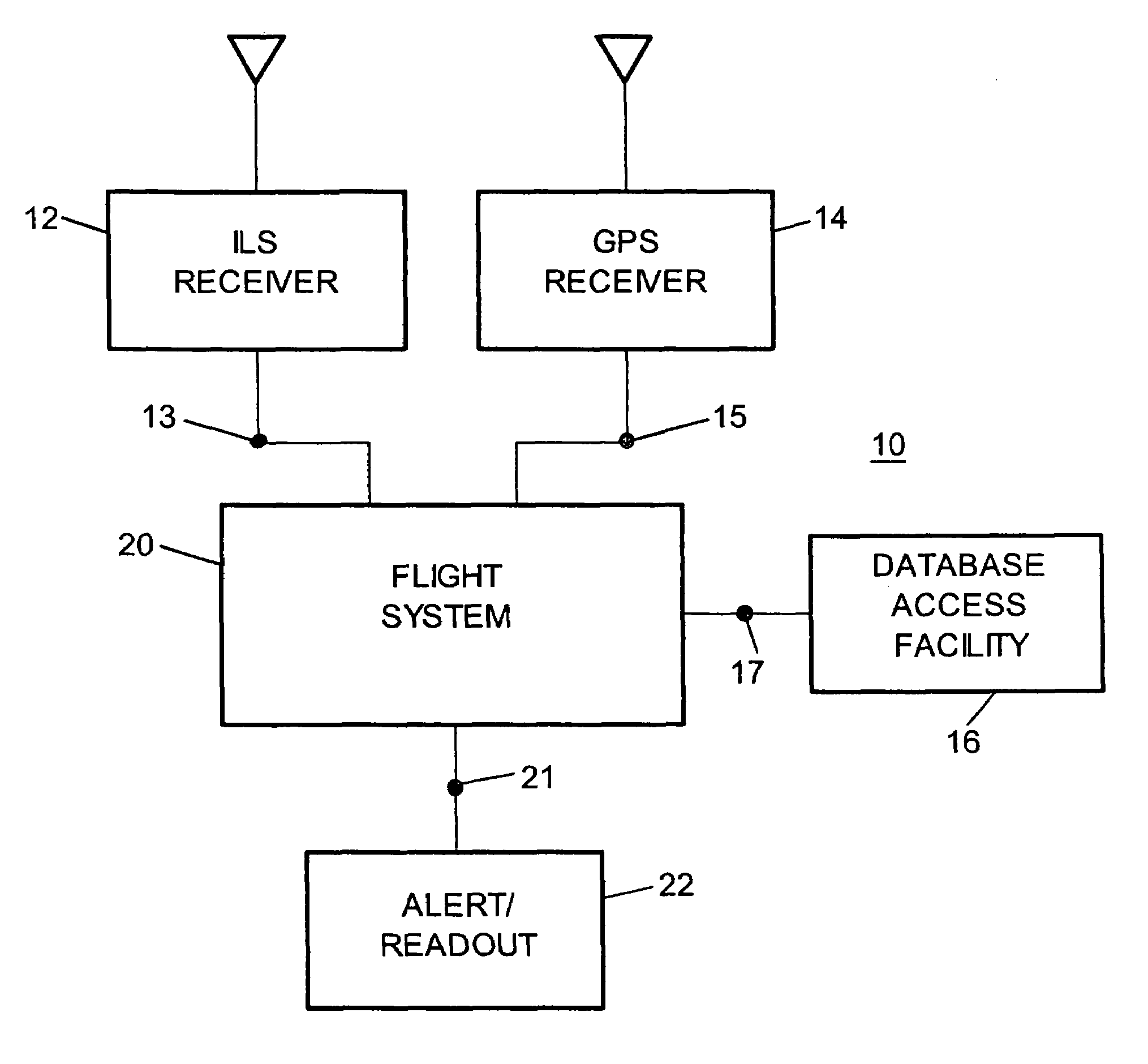
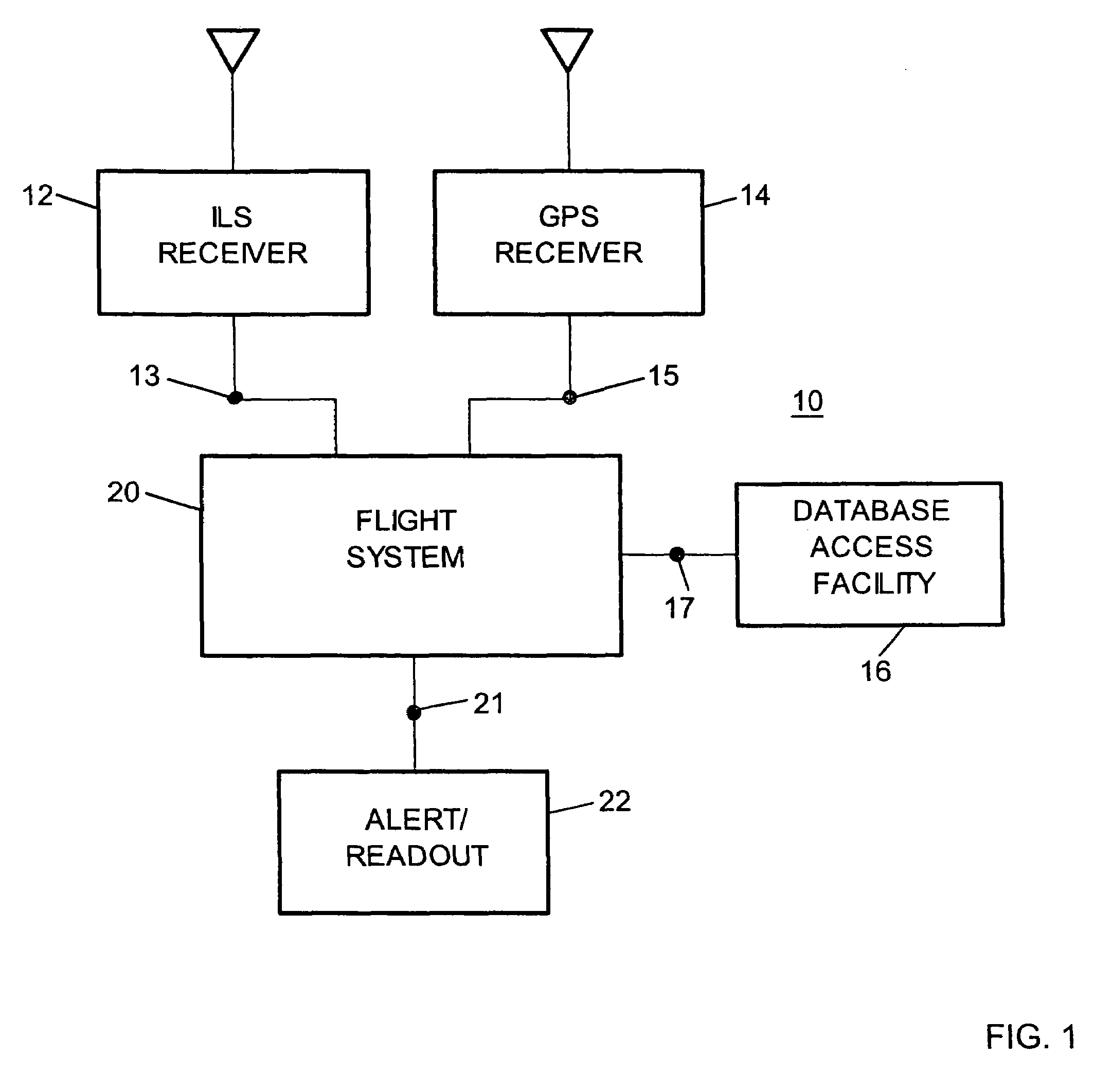
[0028]On a simplified basis, an aircraft approaching a runway with an associated ILS should intersect the ILS glide slope path at a predetermined point in space. For example, an intersection point about four miles from the end of the runway, from which point the aircraft could begin a 3° descent to arrive at the runway surface (this point may be referred to as a final approach fix or “FAF” point). Thus, the ILS may be designed to transmit a discernable signal in space extending from the runway upward at an angle of 3° above horizontal (e.g., a signal in space which is transmitted along the glide slope path, in order to define that path).

[0029]Ideally, this ILS feature of an upwardly angled discernable signal would always be steady, fixed and reliable, so that if an antenna on an aircraft proceeding at the proper altitude received a signal representative of the glide slope path the pilot would know conclusively that the aircraft was then at the proper point in space (e.g., the “inten...


PUM


Abstract

An instrument landing system (ILS) provides signals in space receivable by an aircraft in flight to identify, for example, a point in space at which to start an approach along a glide slope path to a touchdown point on a runway. Atmospheric, ground and other conditions may cause transmission anomalies, so that the ILS signals identify a point in space displaced from its intended position. Systems and methods employed in flight use GPS or other positional data to determine the current displacement of such point, as identified by received ILS signals, from its intended position consistent with ILS specifications. In addition to reception and use of ILS and GPS signals, data on geographic runway location and correct ILS signal in space parameters is used for reference purposes in determining signal in space position discrepancies, glide slope path angular discrepancies, or both. The pilot can be alerted not to rely upon the ILS when discrepancies, which can vary on a short time basis and not be discernable from the ground, are determined to exceed safe limits.

Description

RELATED APPLICATIONS[0001](Not Applicable)FEDERALLY SPONSORED RESEARCH[0002](Not Applicable)BACKGROUND OF THE INVENTION[0003]This invention relates to use of instrument landing systems by instrument-rated aircraft and, more particularly, to verification of the integrity of in-space signals transmitted by an instrument landing system.[0004]Reduced visibility, due to adverse weather conditions, may make it difficult or impossible for a pilot to rely upon visual observation of the landing site to safely land an aircraft. The problem has been addressed by Instrument Landing System (ILS) installations at many airports. Such systems rely upon transmission of a pattern of signals in space. Equipment installed on board instrument-rated aircraft is arranged to receive the ILS signals. On a simplified overview basis, reception by an aircraft of a particular ILS signal (i.e., representative of a specific feature of a pattern in space of ILS approach signals) is intended to indicate to the pilo...

Claims


Application Information

Patent Timeline
Patent Type & Authority Patents(United States)
IPC IPC(8): G05D1/00G06F19/00
CPCG01S1/022G01S1/18G01S19/15
Inventor MARCUM, FRANK
Owner MARCUM FR
Why Eureka
Try Eureka