A Dual-Channel Directional Modulation System Based on Four-Dimensional Antenna Array
A directional modulation, antenna array technology, applied in diversity/multi-antenna systems, phase-modulated carrier systems, radio transmission systems, etc., can solve problems such as transmission rate limitation, inability to arbitrarily adjust the direction of signal transmission, and phase shifters increasing system costs. , to achieve the effect of low cost, good security communication effect, simple and low structure
- Summary
- Abstract
- Description
- Claims
- Application Information
AI Technical Summary
Problems solved by technology
Method used
Image
Examples
Embodiment 1
[0025] Embodiment 1: Directional modulation of dual QPSK signals based on 20-element four-dimensional linear array
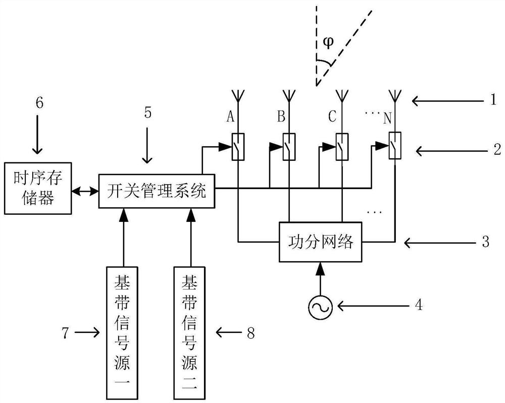
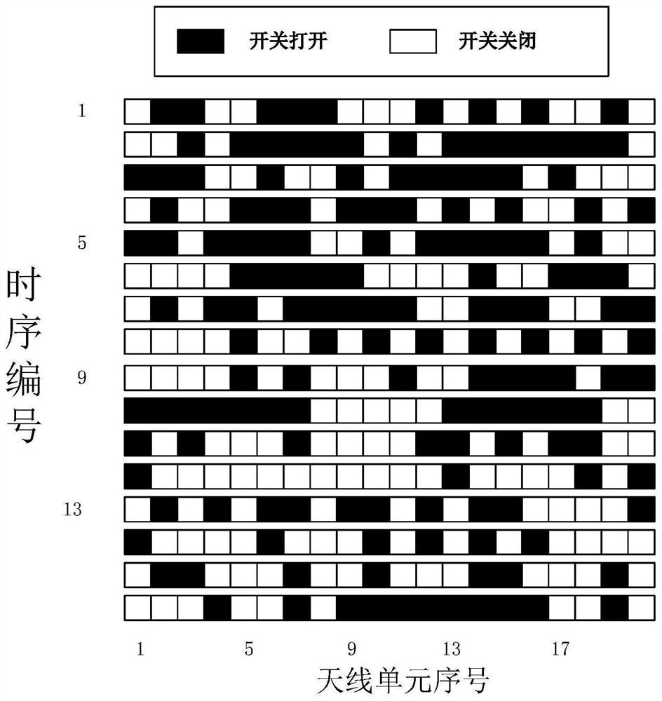
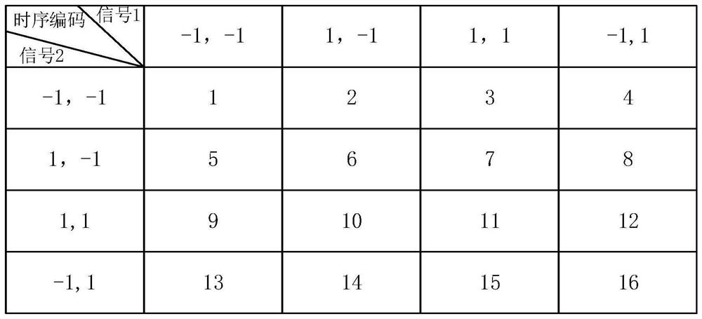
[0026] Based on the basic scheme, one can construct as reference figure 1 The QPSK modulation system shown. In this embodiment, 20 omnidirectional array units are used to form a time-modulated antenna array. The transmitter system mainly includes 20-unit uniform linear antenna array 1, radio frequency modulation switch 2, power distribution network 3, local oscillator source 4, switch management system 5, timing memory 6, baseband signal source 1 7, baseband signal source 2 8, etc. . In this embodiment, we determine the signal source in the basic scheme as a QPSK signal source, the antenna unit is an ideal omnidirectional radiation antenna, and the distance between adjacent antenna units is d=0.5λ, where λ is the wavelength of the transmitted signal. The 20 antenna units of the antenna array are respectively controlled by 20 radio frequency modulation switche...
Embodiment 2
[0027] Embodiment 2: Directional modulation of dual-channel QPSK signals based on 20-unit four-dimensional arc array
[0028] There are two obvious disadvantages for the linear array: it is impossible to synthesize QPSK signals near the zero-degree direction; it is impossible to synthesize QPSK signals in relatively large angle directions. This is determined by the physical structure of the linear array and cannot be optimized through timing adjustment. In order to overcome the defects of the linear array, in this example, the antenna array in Example 1 is replaced by a circular arc array with 20 elements uniformly distributed, and the distance between adjacent array elements is d=0.5λ, where λ is the wavelength of the transmitted signal, and the radius of the arc is is 6.4λ, and the other structures of the system remain unchanged. The system consists of Figure 6 shown. In order to reflect the advantages of the arc array, this example sets the emission direction as the dir...
PUM
 Abstract
Description
Claims
Application Information
 - R&D
- Intellectual Property
- Life Sciences
- Materials
- Tech Scout
- Unparalleled Data Quality
- Higher Quality Content
- 60% Fewer Hallucinations
Browse by: Latest US Patents, China's latest patents, Technical Efficacy Thesaurus, Application Domain, Technology Topic, Popular Technical Reports.
© 2025 PatSnap. All rights reserved.Legal|Privacy policy|Modern Slavery Act Transparency Statement|Sitemap|About US| Contact US: help@patsnap.com


