Capacitor partial discharge coupling and denoising sensor

A capacitor and sensor technology, which is applied in the field of capacitor partial discharge coupling noise-cancelling sensors, can solve the problems of poor linearity of the ultrasonic method, inability to accurately reflect the changing trend of capacitors, and inability to effectively remove interference signals, etc.

Inactive Publication Date: 2014-01-22
STATE GRID CORP OF CHINA +1
View PDF3 Cites 2 Cited by
  • Summary
  • Abstract
  • Description
  • Claims
  • Application Information

AI Technical Summary

Problems solved by technology

[0002] At present, in the partial discharge monitoring of power capacitors, the pulse current method is affected by the strong interference signals on the space and the line, which makes the system unable to correctly identify the weaker discharge signals. Conventional filtering, freque...

Method used


Image

  • Capacitor partial discharge coupling and denoising sensor
  • Capacitor partial discharge coupling and denoising sensor

Examples


Embodiment

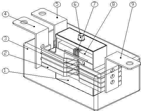
[0011] Example: such as figure 1 As shown, the capacitor partial discharge coupling noise canceling sensor includes two balanced windings 2 , and the two balanced windings 2 are wound on a magnetic core 8 in a symmetrical cross arrangement. One ends of the two balanced windings 2 are respectively connected to the terminal a4 and the terminal b5, and the other ends are connected to the terminal c9 together. The detection winding 7 is wound in the middle of the magnetic core and connected to the output terminal 6 . The magnetic core 8 is placed in the shielding case 1 and fixed by pouring epoxy resin. The connecting terminals a4, b5 and c9 are placed on both sides of the shielding case 1, and the outer ends are exposed outside the shielding case 1. The shielding shell 1 is covered with an impedance shell 3 .

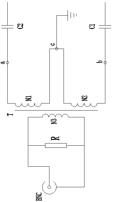
[0012] Such as figure 2 As shown, the capacitor partial discharge coupling noise elimination sensor circuit includes two balanced windings 2 (N1, N2), and a detection ...


PUM


Abstract

The invention relates to a capacitor partial discharge coupling and denoising sensor. The sensor comprises two balancing windings, wherein the two balancing windings are symmetrically and crosswise arranged and wound on a magnetic core; one end of each of the two balancing windings are connected with a connecting terminal a and a connecting terminal b respectively, and the other end of each of the two balancing windings are jointly connected with a connecting terminal c; a detection winding is wound on the middle part of the magnetic core and an output terminal is connected onto the detection winding. Since the technical scheme is implemented, a special coupling and denoising circuit is adopted, and the principle that the polarities of the windings are reverse and the magnetic fluxes are cancelled out is utilized. Interference signals in space and on the circuit can be eliminated through the coupling circuit; the output final signal is a partial discharge signal in the capacitor, so that the insulation level of a power capacitor can be accurately monitored in real time.

Description

technical field [0001] The invention relates to a capacitor partial discharge coupling noise elimination sensor. Background technique [0002] At present, in the partial discharge monitoring of power capacitors, the pulse current method is affected by the strong interference signals on the space and the line, which makes the system unable to correctly identify the weaker discharge signals. Conventional filtering, frequency mixing and other methods cannot effectively remove the interference signals. Therefore, Only the method of ultrasonic monitoring can be used, but the linearity of the ultrasonic method is poor, and it cannot accurately reflect the changing trend of the discharge value inside the capacitor. Contents of the invention [0003] The purpose of the present invention is to provide a capacitor partial discharge coupling denoising circuit that can eliminate the interference signal on the space and the line, and is ready to detect the insulation level of the power...

Claims


Application Information

Patent Timeline
IPC IPC(8): G01R31/12
Inventor 徐文邦陈进顾军刘新宇艾比布勒·赛塔尔邢占礼安斌黄新民周立王德平廖来新杨柱石侯冰
Owner STATE GRID CORP OF CHINA
Why Eureka
Try Eureka