Image processing method and device using photo assistant tool including rotator

a technology of assistant tool and image processing device, which is applied in the direction of cameras, television systems, instruments, etc., can solve the problem of small distance between photographic points

Inactive Publication Date: 2009-06-16
SONY COMPUTER ENTERTAINMENT INC
View PDF14 Cites 22 Cited by
  • Summary
  • Abstract
  • Description
  • Claims
  • Application Information

AI Technical Summary

Problems solved by technology

However, depending on the intervals of continuous shots a distance between points of view, that is, a distance between photographic points may become small.

Method used


Image

  • Image processing method and device using photo assistant tool including rotator
  • Image processing method and device using photo assistant tool including rotator
  • Image processing method and device using photo assistant tool including rotator

Examples


embodiment 1

[0033]A photographic system according to Embodiment 1 of the present invention uses a photo assistant tool including a plurality of imaging sections for parallax image photography. Stereoscopic photography is carried out while a rotator provided with the plurality of imaging sections is being rotated, thereby realizing the photography of omnidirectional parallax images and providing a binocular stereoscopic vision of such images.

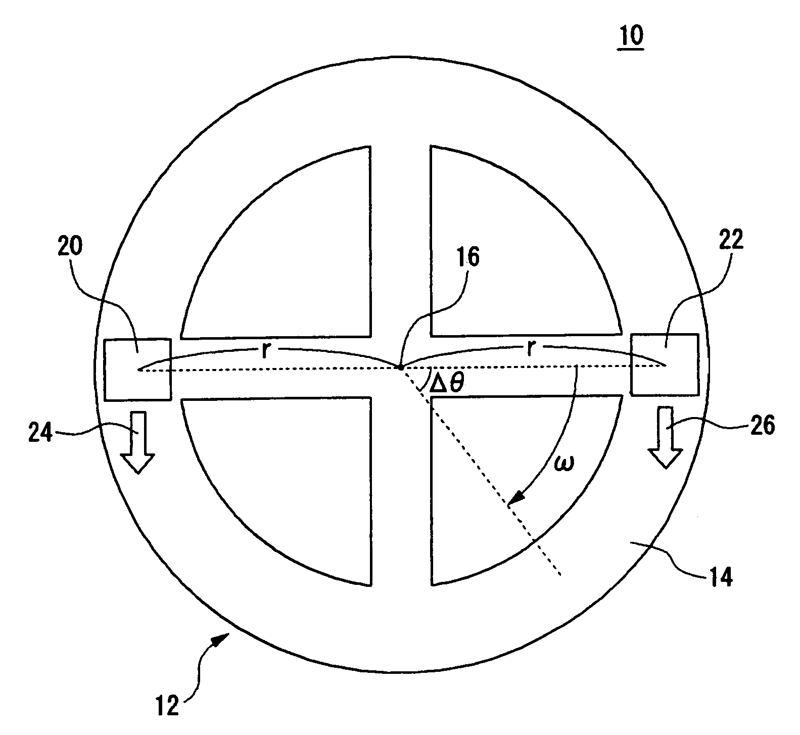
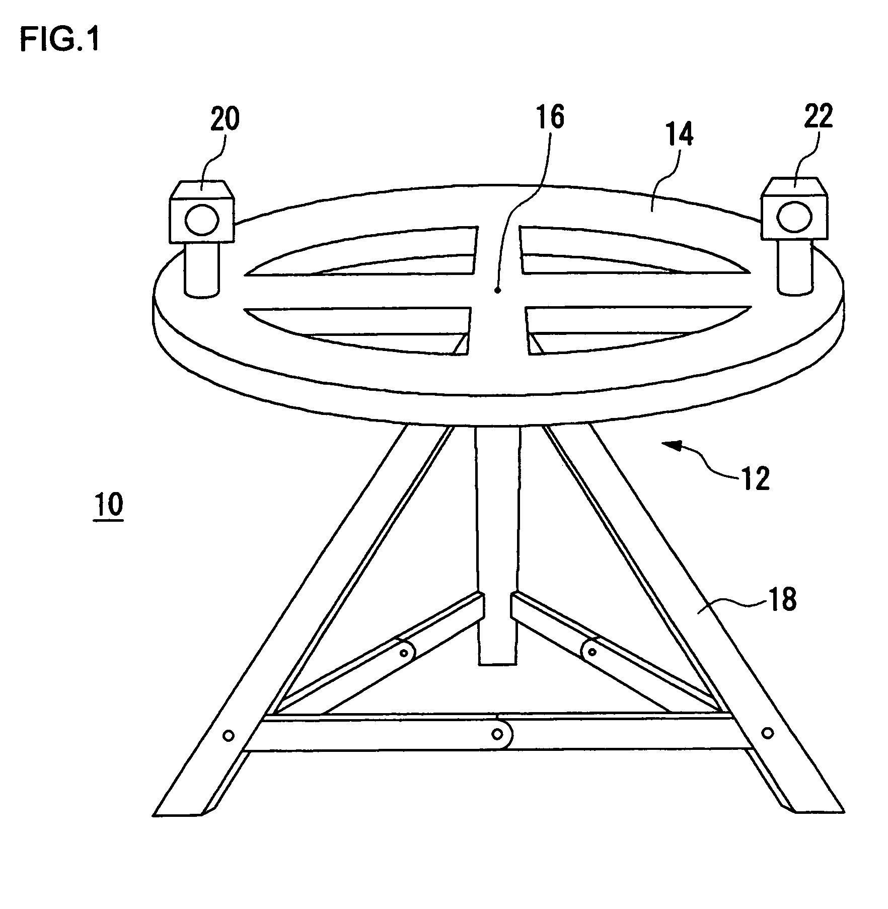
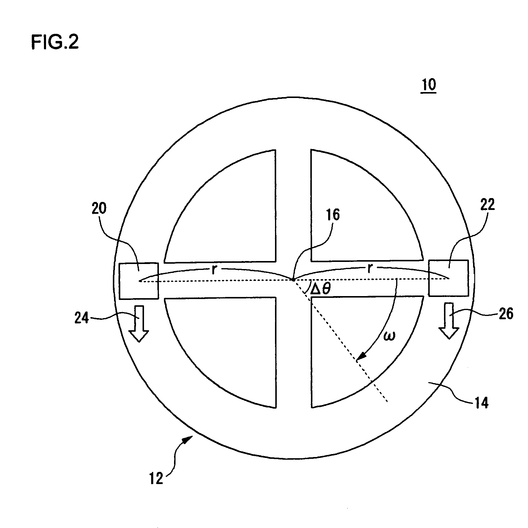
[0034]FIG. 1 shows the outer appearance of a photo assistant tool in a photographic system. A photo assistant tool 12 constituting a photographic system 10 mainly includes: a rotator 14; a plurality of imaging sections 20 and 22; and a support base 18. The rotator 14 is formed by a ring-shaped member and is rotatably supported from its bottom face side with a center 16 of the ring as a center of rotation. The rotator 14 is supported by the support base 18. At the same time, the rotation of the rotator 14 is controlled by a control section not shown. A rotati...

embodiment 2

[0053]The photo assistant tool 12 in Embodiment 2 of the present invention differs from that in Embodiment 1 in that it has only one imaging section provided for the rotator 14. A method of acquiring parallax images and a method of acquiring an omnidirectional image differ from those of Embodiment 1.

[0054]FIG. 10 shows the outer appearance of the rotator 14 according to Embodiment 2 when viewed from above. In this embodiment, one imaging section 40 is provided at the approximate central position on the right side of the upper surface of the rotator 14 in FIG. 10. The imaging section 40 rotates on its axis independently of the rotation of the rotator 14. The continuous shooting is performed while the imaging section 40 is rotating, thereby obtaining an omnidirectional image. The entire rotator 14 also rotates independently of and in addition to the rotation of the imaging section 40. However, the rotation of the rotator 14 in this embodiment is not continuous as in Embodiment 1; it s...

embodiment 3

[0058]Embodiment 3 of the present invention is common to Embodiment 1 in that the rotator 14 of the photo assistant tool 12 is provided with two imaging sections. However, Embodiment 3 differs from Embodiment 1 in that photographic directions of the two imaging sections are different from each other.

[0059]FIG. 13 shows the outer appearance of the rotator 14 according to Embodiment 3 when viewed from above. On the upper face of the rotator 14, the first imaging section 20 and the second imaging section 22 are provided as a plurality of imaging sections as in Embodiment 1 of the present invention. However, in contrast to Embodiment 1, the first imaging section 20 and the second imaging section 22 are both provided on the right side in FIG. 13 so that their photographic directions 24 and 26 are opposite to each other. The photo assistant tool 12 in this embodiment mainly has three operation modes.

[0060]In the first mode, after taking images in two directions in the illustrated state, t...


PUM


Abstract

A photographic method of a stereoscopic image or an omnidirectional image has hidden potential of creating innovative video systems and video services that have never existed before. A photo assistant tool includes: a rotator formed by a ring-shaped circular member; a first imaging section and a second imaging section provided on an upper face of the rotator; and a support base. The first imaging section and the second imaging section take a pair of parallax images. At the same time, by continuous shots taken by the first imaging section and the second imaging section while the rotator is being rotated about a center as a center of rotation, omnidirectional parallax images are obtained. Furthermore, by continuous shots taken by the first imaging section and the second imaging section while the rotator is being continuously rotated, a motion picture made up of omnidirectional parallax images as frames is taken.

Description

BACKGROUND OF THE INVENTION[0001]1. Field of the Invention[0002]The present invention relates to a photo assistant tool and an image processing device. The present invention relates, in particular, to a technique for realizing stereoscopic photography and omnidirectional image photography.[0003]2. Description of the Related Art[0004]A stereoscopic image is obtained by stereoscopic photography for photographing the same subject from different points of view. Owing to a parallax generated in the stereoscopic image, a depth can be represented to realize a binocular stereoscopic vision. The binocular stereoscopic vision can be achieved by a method of using a dedicated apparatus such as liquid crystal shutter glasses, by stereoscopic viewing with naked eyes by a cross-eyed method or a parallel-viewing method without using any special apparatuses, or the like. Moreover, a 360-degree image, that is, an omnidirectional image can be obtained by capturing an image with a so-called omnidirecti...

Claims


Application Information

Patent Timeline
Patent Type & Authority Patents(United States)
IPC IPC(8): H04N5/225H04N13/02H04N15/00G03B15/00H04N13/239G03B17/00G03B17/56G03B35/12G03B37/00H04N5/222
CPCH04N5/2254H04N13/0239H04N13/239
Inventor WADA, SHINYASUZUKI
Owner SONY COMPUTER ENTERTAINMENT INC
Why Eureka
Try Eureka