Detection and control of diaphragm collapse in condenser microphones

a technology of condenser microphone and diaphragm, which is applied in the direction of transducer details, electrostatic transducer microphone, electrical transducer, etc., can solve the problems of microphone in collapse state, and the detection and control circuit adapted for use in condenser microphones have not yet been disclosed

Active Publication Date: 2009-06-16
TDK CORPARATION
View PDF15 Cites 117 Cited by
  • Summary
  • Abstract
  • Description
  • Claims
  • Application Information

AI Technical Summary

Benefits of technology

[0029]In preferred embodiments, the transducer element has a silicon transducer or MEMS transducer. The silicon transducer may be implemented on a first silicon substrate, while the collapse detection element and the collapse control element are implemented on a second silicon substrate. The collapse detection element and the collapse control element are preferably monolithically integrated on a single die. The die may further comprise a preamplifier operatively coupled to the transducer element.
[0030]As indicated above, the preferred embodiments of the collapse detection element and collapse control element include electronic circuits which may make mechanical solutions obsolete and allow a higher degree of freedom in the mechanical construction of the transducer element. This is a significant design advantage with silicon and MEMS-based microphones. In addition, electronic solutions offer larger flexibility in a practical setting of a predetermined threshold level associated with a certain sound pressure level or a certain separation between the diaphragm and back-plate where the collapse control element is triggered. Accordingly, electronic circuit based collapse detection element allow simple customization to fit needs of any particular application.

Problems solved by technology

It is well-known that electrostatic actuators and sensors may enter an undesired so-called collapsed state under certain operating conditions such as, e.g., when exposed to extraordinarily high sound pressure levels or a mechanical shock.
When a sum of these forces exceeds a predetermined critical value, an opposing force provided by a diaphragm suspension will be insufficient to prevent the diaphragm from approaching and contacting the back-plate, causing the microphone to enter a collapsed state.
However, a collapse detection and control circuit adapted for use in condenser microphones has not yet been disclosed.

Method used


Image

  • Detection and control of diaphragm collapse in condenser microphones
  • Detection and control of diaphragm collapse in condenser microphones
  • Detection and control of diaphragm collapse in condenser microphones

Examples


Embodiment Construction

[0018]While this invention is susceptible of embodiment in many different forms, there is shown in the drawings and will herein be described in detail preferred embodiments of the invention with the understanding that the present disclosure is to be considered as an exemplification of the principles of the invention and is not intended to limit the broad aspect of the invention to the embodiments illustrated.

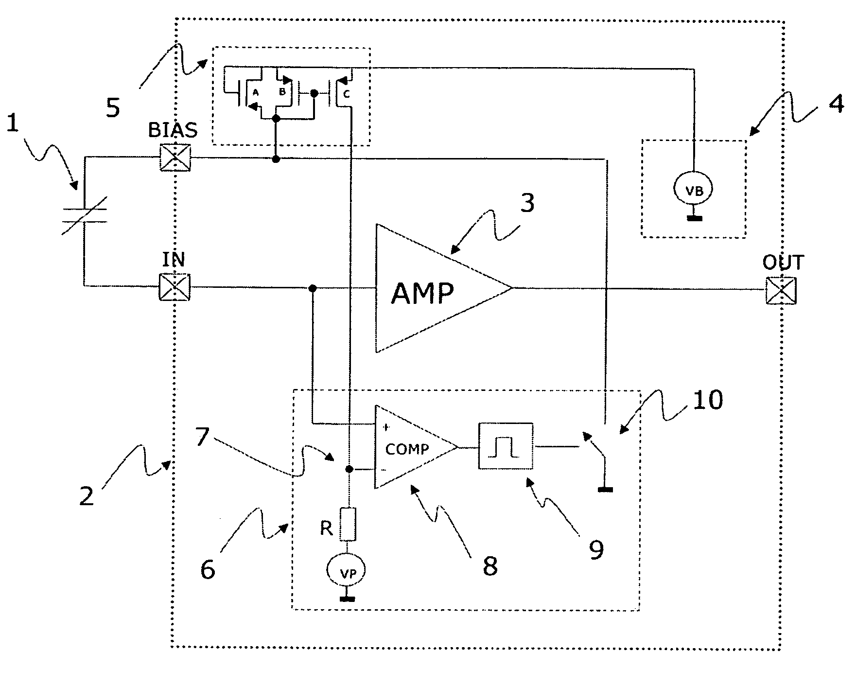
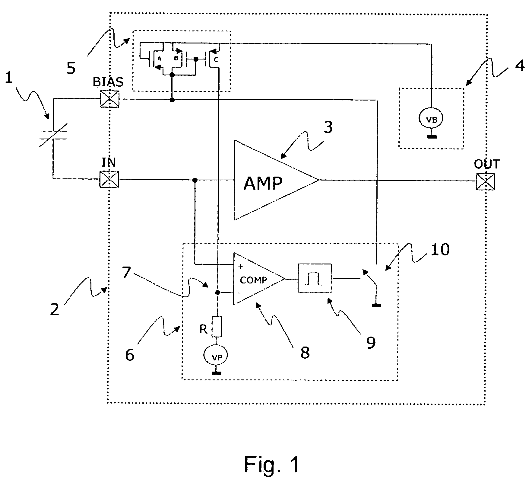
[0019]According to one embodiment of the invention, a condenser microphone is provided that has a transducer element. The transducer element includes a diaphragm having an electrically conductive portion. A back-plate of the transducer element has an electrically conductive portion. A DC bias voltage element of the transducer element is operatively coupled to the diaphragm and the back-plate. A collapse detection element of the transducer element is adapted to determine a physical parameter value related to a separation between the diaphragm and the back-plate. A collapse contro...


PUM


Abstract

A condenser microphone is provided having a transducer element. A diaphragm has an electrically conductive portion. A back-plate has an electrically conductive portion. A DC bias voltage element is operatively coupled to the diaphragm and the back-plate. A collapse detection element is adapted to determine a physical parameter value related to a separation between the diaphragm and the back-plate. A collapse control element is adapted to control the DC bias voltage element based on the determined physical parameter value.

Description

PRIORITY[0001]This application claims the benefit of priority under 35 U.S.C. §119 of provisional application Ser. No. 60 / 572,763, filed May 21, 2004, the contents of which are hereby incorporated by reference in their entirety as if fully set forth.FIELD OF THE INVENTION[0002]The present invention relates to a condenser microphone having a detection element adapted to determine a physical parameter value related to a separation between a transducer element diaphragm and a back-plate, and a collapse control element adapted to control a DC bias voltage of the transducer element based on the determined physical parameter value.BACKGROUND OF THE INVENTION[0003]It is well-known that electrostatic actuators and sensors may enter an undesired so-called collapsed state under certain operating conditions such as, e.g., when exposed to extraordinarily high sound pressure levels or a mechanical shock.[0004]The collapsed state is characterized by a “collapse” or sticktion between the diaphragm...

Claims


Application Information

Patent Timeline
Patent Type & Authority Patents(United States)
IPC IPC(8): H04R3/00H04R19/04
CPCH04R3/007H04R19/04
Inventor STENBERG, LARS JORNPOULSEN, JENS KRISTIANVAN HALTEREN, AART ZEGER
Owner TDK CORPARATION
Why Eureka
Try Eureka