Holding device for fixing a lamp bulb and associated lamp

a technology for holding devices and lamp bulbs, which is applied in the direction of discharge tube/lamp details, discharge tube main electrodes, incadescent cooling arrangements, etc., can solve the problem of reducing the size of the reflector neck, and achieves simple securing, simple and reliable low-cost, and easy clamping of the clamp part.

Inactive Publication Date: 2009-06-23
OSRAM GMBH
View PDF15 Cites 3 Cited by
  • Summary
  • Abstract
  • Description
  • Claims
  • Application Information

AI Technical Summary

Benefits of technology

[0004]It is an object of the present invention to provide a holding device for fixing a lamp bulb which is simple to mount and can be produced well in an automated process.
[0007]The invention makes possible the fixing of the lamp bulb of a lamp pinched at one end by means of a holding device, also known as a holding element, the holding function of which is realized either by a form fit or by spring force. Particularly suitable for this is a spring clip which is designed as a clip mechanism. This makes the lamp particularly suitable for simple mechanical production appropriate for automated equipment on production lines without hot processes, such as for example sealing-in, welding or soldering. Moreover, long process times, for example for drying, baking or pumping, are avoided. The lamp bulb is fixed without cement, by means of two clips, preferably made of metal or else plastic.
[0027]A simple, reliable and low-cost solution for the securing of the enveloping part is that the clamp part comprises clamps distributed over the circumference or a peripheral clamp strip. In particular, the clamp strip is a deformable ring, which is produced in particular from metal or plastic, so that a very simple securing is possible by the clamp strip first being already angled away at the lower rim, and being drawn up over the base contact insulator until it comes up against the projecting segment. As soon as the enveloping part is fitted on, the ring, preferably made of aluminium, can be mechanically formed onto the segment, and in this way fix the rim of the enveloping part.
[0028]A damping means is preferably inserted between the clamp part and the upper contact surface of the rim of the enveloping part. This is in particular a kind of O-ring, for example made of an elastomer. In this way, the material of the enveloping part, advantageously glass or aluminium, is protected from being damaged during the forming-on process. A further advantage is that, as a result, the connecting force between the enveloping part and the segment is retained without any play over the service life of the lamp. On account of the damping ring, the clamping of the clamp part can be increased without any risk, and consequently the connection can be made more reliable.

Problems solved by technology

A disadvantage of this is that the dimensioning of the neck of the reflector must also be made to match the standard dimensions of the base.

Method used


Image

  • Holding device for fixing a lamp bulb and associated lamp
  • Holding device for fixing a lamp bulb and associated lamp
  • Holding device for fixing a lamp bulb and associated lamp

Examples


Embodiment Construction

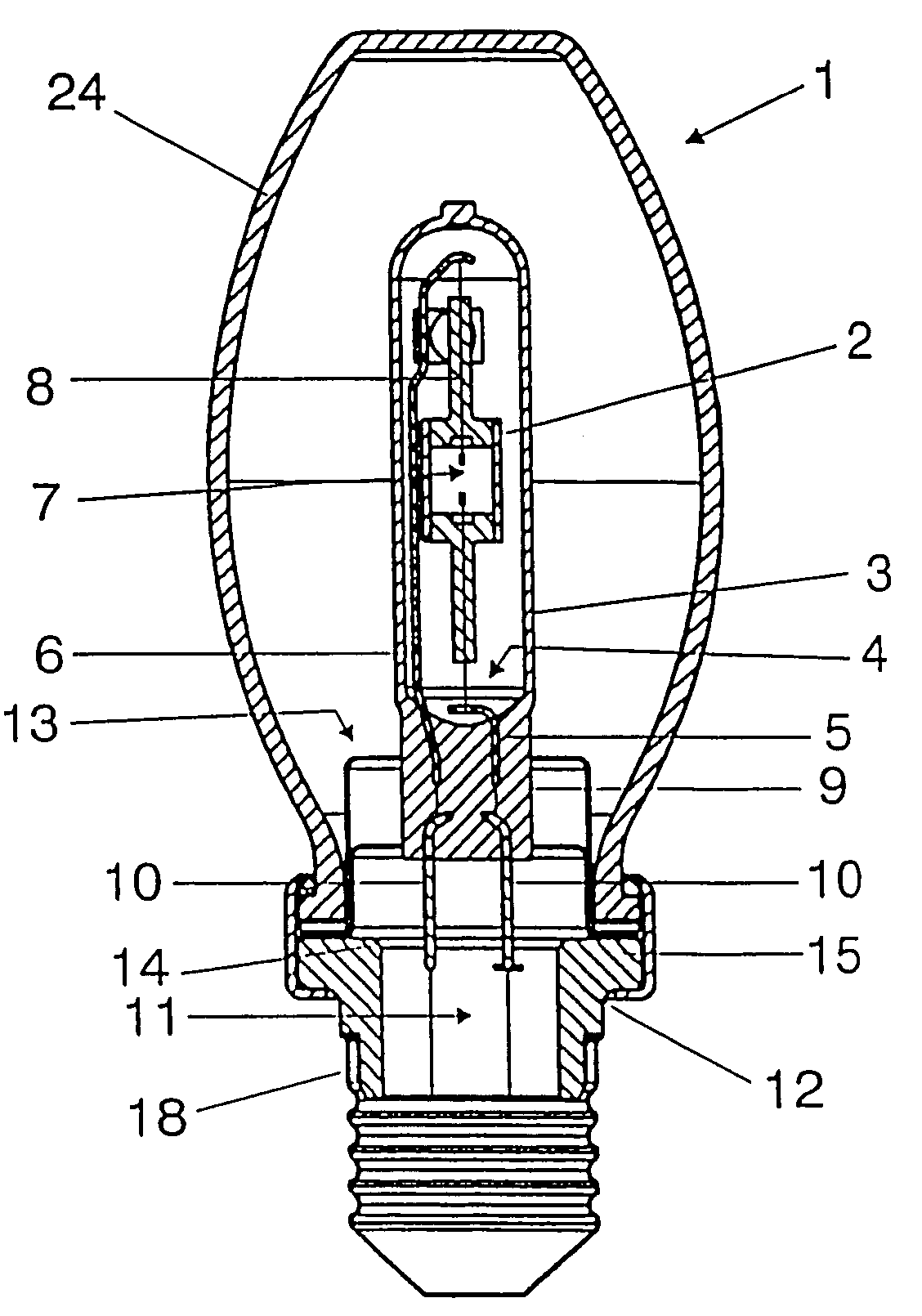
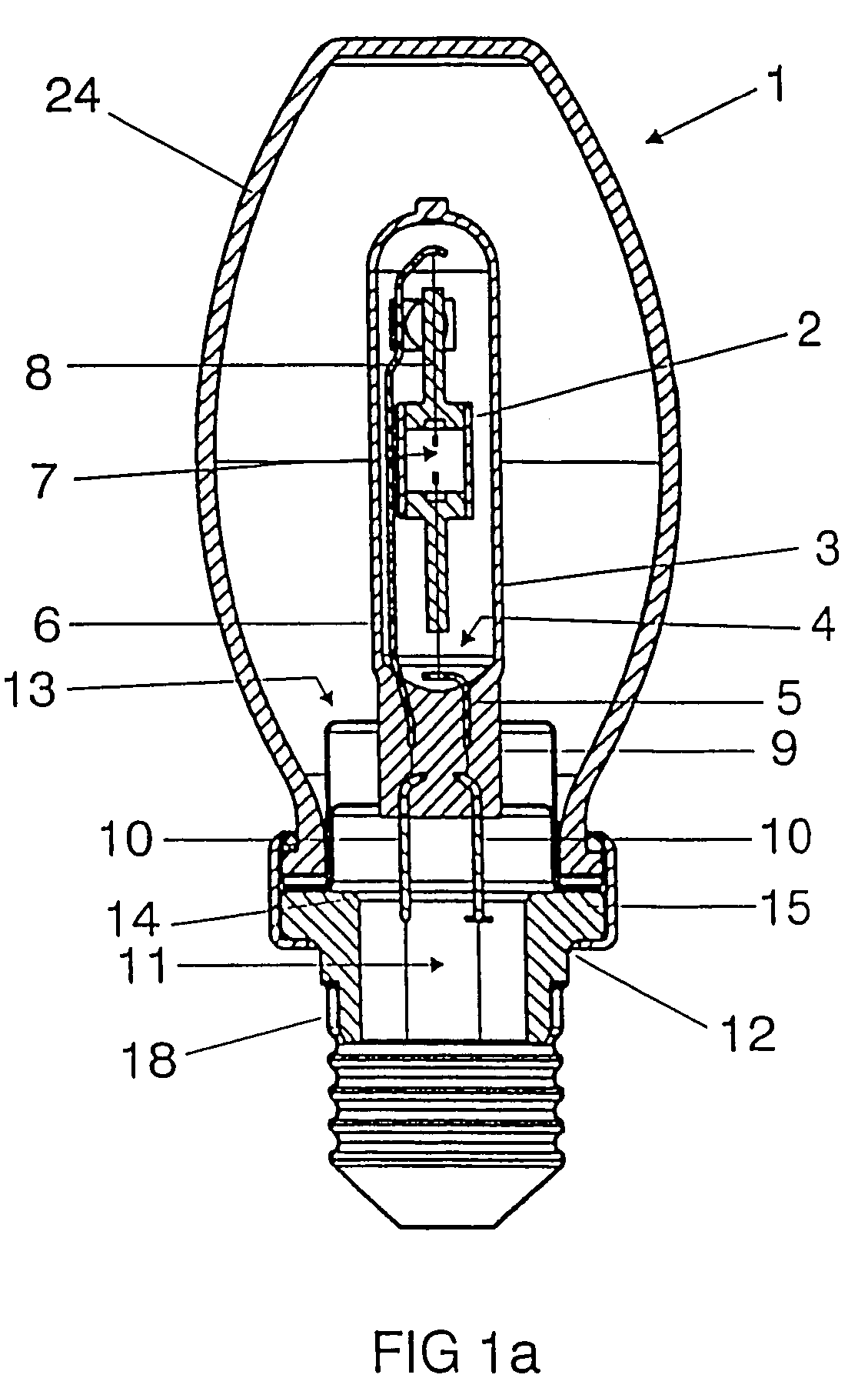
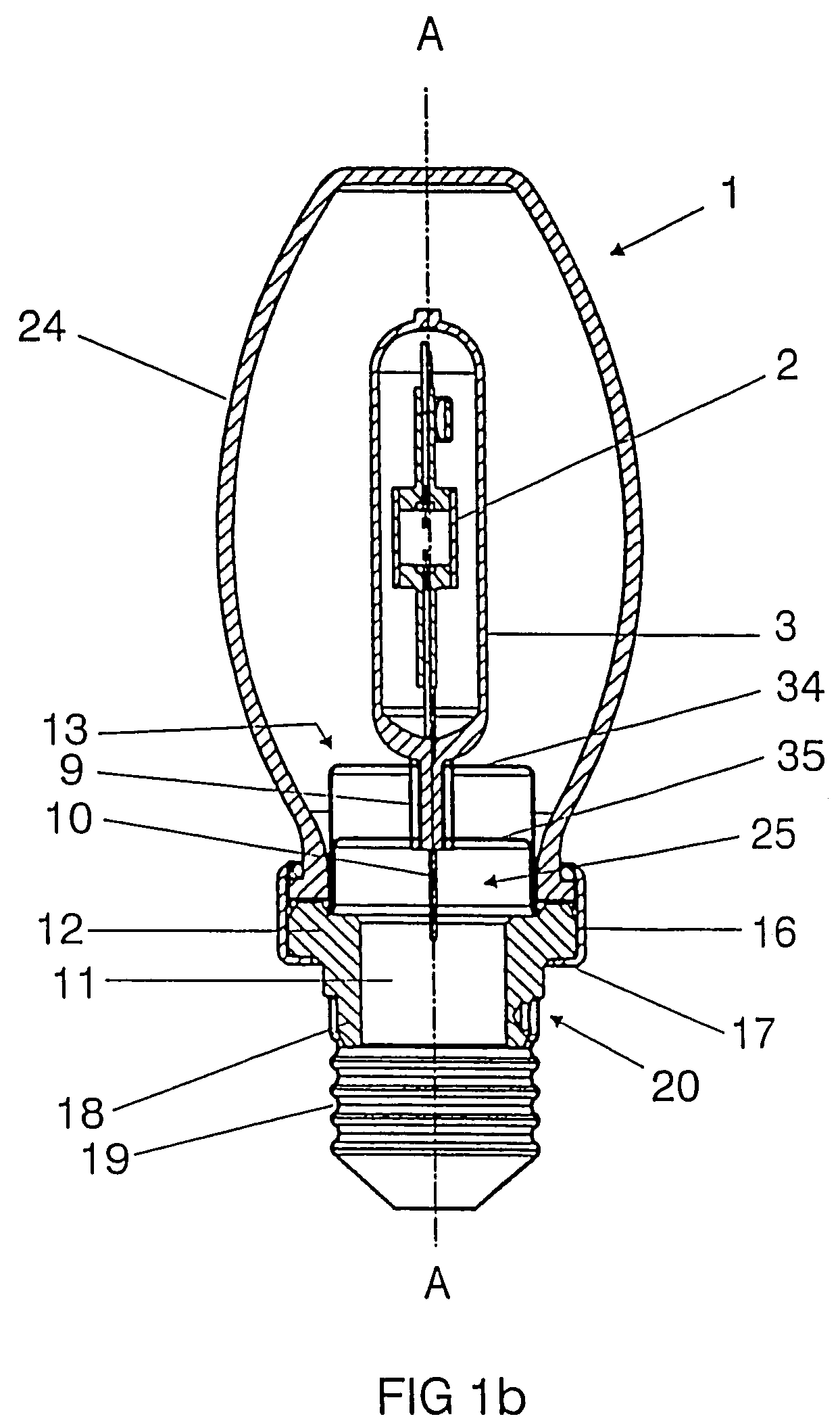
[0045]FIGS. 1 and 2 show an exemplary embodiment of a metal halide lamp 1, respectively turned by 90° with respect to each other. A ceramic discharge vessel 2, which is closed at two ends, is arranged in a longitudinally extended manner in the lamp axis A. It is closely surrounded by an outer bulb 3, which is pinched at one end and is produced from hard glass or quartz glass. A frame 4 with short and long leads 5, 6 secures the discharge vessel 2 in the outer bulb 3. The electrodes 7 inside the discharge vessel are connected to the leads 5, 6 by means of lead-throughs 8. Said leads are connected in the region of a pinch 9, which seals the outer bulb 3, to external supply leads 10. The pinch 9 of the outer bulb is located above a hollow space 11 of a base contact insulator 12 made of ceramic and is secured by a holding element 13 made of metal. The base contact insulator may also be produced from some other material, for example a plastic which can withstand great loading.

[0046]The h...


PUM


Abstract

A holding device for fixing a lamp bulb comprises at least one clip element, the clip element, referred to as the main clip, having a peripheral flange as a supporting surface, which is adjoined at its inner rim by a peripheral side wall with a given height H, which is preferably cylindrically shaped, its free end forming a closing-off cover, the cover having a clearance which is adapted to the portion of the lamp bulb that is to be fixed.

Description

TECHNICAL FIELD[0001]The invention relates to a holding device for fixing a lamp bulb and to an associated lamp. Here it concerns in particular high-pressure discharge lamps, preferably metal halide lamps, but also for example halogen incandescent lamps. Often a longitudinally extended, in particular ceramic, discharge vessel is used as the lamp bulb. Details of a lamp of this type are disclosed in the still unpublished PCT / DE2004 / 001710 which is incorporated by reference.BACKGROUND ART[0002]U.S. Pat. No. 5,576,591 already discloses a holding device for fixing a lamp bulb and associated lamp which is made up of three bulbs. It has a ceramic adapter, which is mounted on a screw base. Atmospheric pressure prevails between the enveloping bulb and the outer bulb.[0003]U.S. Pat. No. 6,319,046 describes a high-pressure lamp with a base at one end in which the outer bulb is surrounded by a reflector. The base is fastened directly to the neck of the reflector by means of crimping. A disadva...

Claims


Application Information

Patent Timeline
Patent Type & Authority Patents(United States)
IPC IPC(8): H01J5/48H01J5/50H01J61/34H01K1/46
CPCH01J5/48H01J61/34H01K1/46H01J61/82
Inventor ARNDT, JOACHIMFIDLER, UWEHERB, MARKUS
Owner OSRAM GMBH
Why Eureka
Try Eureka