
Light emitting device drive controller, and a light emitting device driving apparatus

a technology of light emitting devices and drive controllers, which is applied in the direction of static indicating devices, identification means, instruments, etc., can solve the problems of reducing the power supply capacity of batteries, affecting the operation efficiency of microcomputers, and affecting the operation of electronic devices that should be performed under normal circumstances or operate improperly, so as to reduce the number of ports.

Active Publication Date: 2009-06-23
SEMICON COMPONENTS IND LLC
View PDF4 Cites 9 Cited by
  • Summary
  • Abstract
  • Description
  • Claims
  • Application Information

AI Technical Summary

Benefits of technology

[0021]It is therefore an object of the present invention to provide a light emitting device drive controller and light emitting device driving apparatus that can reduce the number of ports necessary for selectively driving tour or five light emitting devices as compared to the conventional case.

Problems solved by technology

The power supply capacity from the battery is reduced as the electronic device is utilized by a user and will not be able to supply power at a level that can operate the electronic device normally over time.
During the course of the normal operation of the electronic device, if the battery cannot supply power that can operate the electronic device normally, the electronic device stops operation that should be performed under normal circumstances or operates improperly.
Therefore, the total number of the ports of the microcomputer 6 is increased proportionally to the number of the LEDs and the size of the microcomputer 6 may be enlarged, which is problematic.
However, as described in the light emitting device driving apparatuses of FIGS. 12 and 13, if the total number of the LEDs is four or five, the number of the control ports must be four or five to turn on the LEDs and it is difficult to make the number of the control ports three or less.
Therefore, in the light emitting device driving apparatus that controls the lighting of the four or five LEDs, the number of the control ports of the microcomputers 6, 106 cannot be reduced to three or less and it is problematic that the sizes and costs cannot be reduced in the microcomputers 6, 106.
The number cannot also be reduced for the wirings connecting a display substrate provided with the LEDs and a substrate provided with the microcomputers 6, 106, and it is problematic that the costs of the apparatus itself cannot be reduced.

Method used


Image

  • Light emitting device drive controller, and a light emitting device driving apparatus
  • Light emitting device drive controller, and a light emitting device driving apparatus
  • Light emitting device drive controller, and a light emitting device driving apparatus

Examples


Embodiment Construction

[0041]With the description of this specification and the accompanying drawings, at least the following matters will become apparent.

FIRST IMPLEMENTATION

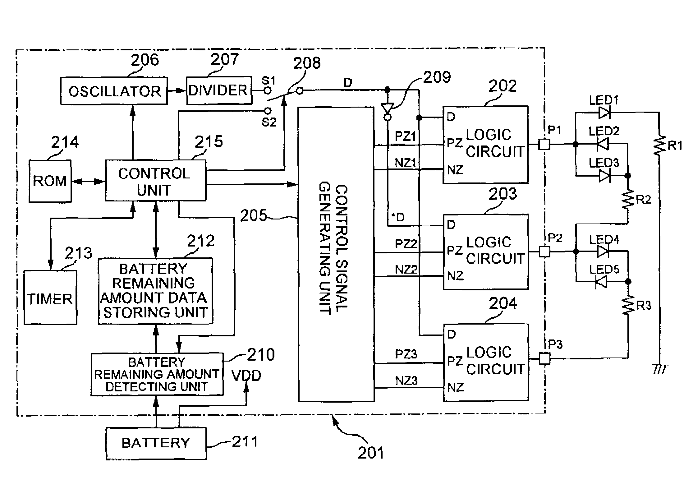
[0042]With reference to FIG. 1, description will be made of a light emitting device drive controller and a light emitting device driving apparatus of the present invention. FIG. 1 is a circuit block diagram of the light emitting device driving apparatus of the present invention. In FIG. 1, a configuration surrounded by a dot-and-dash line on the page shows the light emitting device drive controller, which is constituted by an integrated circuit, for example, a microcomputer with a controlling function of turning on / off light emitting devices and which is disposed on a first printed board (not shown) for driving the light emitting devices. On the other hand, a rightward configuration not surrounded by the dot-and-dash line on the page is external components of the integrated circuit, which is disposed on a second printed board for dis...


PUM


Abstract

A light emitting device drive controller is disclosed that comprises a first port that is connected to one end of a first light emitting device group where two light emitting devices are connected in parallel in the opposite directions; a second port that is connected to the other end of the first light emitting device group as well as connected to one end of a second light emitting device group where two light emitting devices are connected in parallel in the opposite directions; a third port that is connected to the other end of the second light emitting device group; and a port state setting unit that selectively sets each of the first, second, and third ports to any one of a state of a first voltage, a state of a second voltage which is less than the first voltage, and a high impedance state for each consecutive predetermined period, wherein the light emitting device drive controller drives selectively the light emitting devices constituting the first light emitting device group and the second light emitting device group in response to the states of the first, second, and third ports.

Description

CROSS-REFERENCE TO RELATED APPLICATIONS[0001]The present application claims priority from Japanese Patent Applications No. 2005-125267 filed on Apr. 22, 2005, which is herein incorporated by reference.BACKGROUND OF THE INVENTION[0002]1. Field of the Invention[0003]The present invention relates to a light emitting device drive controller and a light emitting device driving apparatus that are suitable to check a changing state of a predetermined factor (e.g., a remaining amount level of a voltage value of a battery) with an ON / OFF state of a light emitting device.[0004]2. Description of the Related Art[0005]A portable electronic device (e.g., notebook personal computer) is equipped with a battery and is supplied with power from the battery to operate. The power supply capacity from the battery is reduced as the electronic device is utilized by a user and will not be able to supply power at a level that can operate the electronic device normally over time. During the course of the norm...

Claims


Application Information

Patent Timeline
Patent Type & Authority Patents(United States)
IPC IPC(8): G08B5/22G08B21/00H05B41/00G09G3/14H01L33/00
CPCG01R31/3682H05B33/0803G01R31/3646H05B45/30G09F9/33G09G3/20G09G3/30
Inventor YONEZAWA, YOSHIAKI
Owner SEMICON COMPONENTS IND LLC
Learn More