Method of memory space configuration

a memory space and configuration technology, applied in the field of memory system access, can solve the problem of inefficiency of the data access system, and achieve the effect of enhancing data access efficiency

Active Publication Date: 2009-06-23
VIA TECH INC
View PDF1 Cites 26 Cited by
  • Summary
  • Abstract
  • Description
  • Claims
  • Application Information

AI Technical Summary

Benefits of technology

[0009]The present invention provides a data accessing method for enhancing data accessing efficiency.

Problems solved by technology

However, the data bus is idle during those clock cycles and latency, as a result, the data access system is inefficient.

Method used


Image

  • Method of memory space configuration
  • Method of memory space configuration
  • Method of memory space configuration

Examples


Embodiment Construction

[0019]Reference will now be made in detail to the present preferred embodiments of the invention, examples of which are illustrated in the accompanying drawings. Wherever possible, the same reference numbers are used in the drawings and the description to refer to the same or like parts.

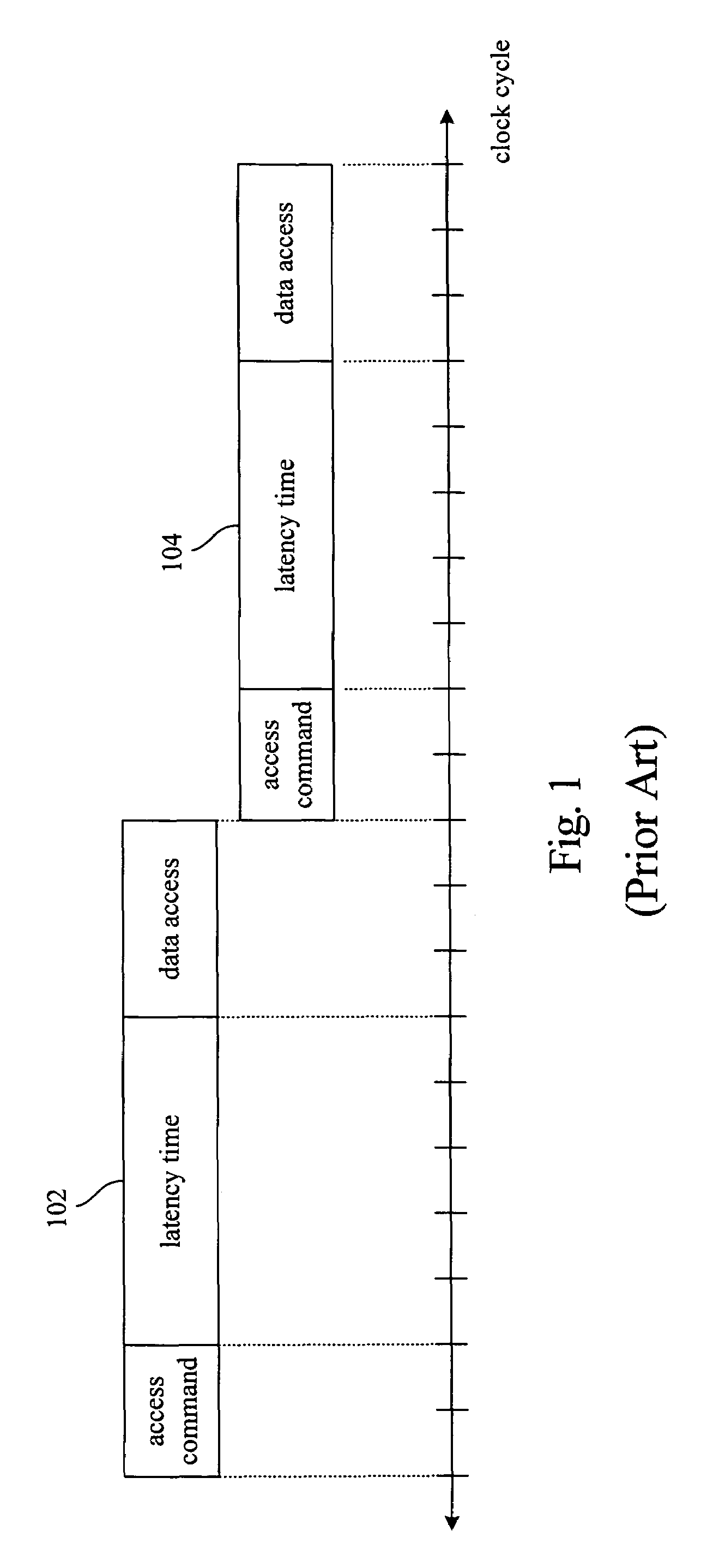
[0020]In accordance with the conventional data storing method, the continuous data (e.g. program codes of the same application program) are generally stored into a continuous memory location. That is to say, even if the memory unit comprises many memory ranks, these continuous data may very likely be stored into the same memory rank. Thus, an accessible data quantity in a continuous access operation is limited by the size of the memory page in a memory rank. If a desired data quantity in the access operation is exceeding the memory page size, the utility rate of the data bus will be widely degraded due to the frequently pre-charging of the old memory page and activating the new memory page.

[0021]FIG....


PUM


Abstract

A method is disclosed for utilizing at least one bit within the logical address code of a memory unit formed by Dynamic Random Access Memory (DRAM) to be the control code for interleaving the memory space to different memory ranks. First, the distributive rule of the data is defined. Next, the data is distributed to the memory ranks that the data belongs to according to the rule. Then, the data is physically accessed in one of the memory ranks.

Description

RELATED APPLICATIONS[0001]The present application is based on, and claims priority from, Taiwan Application Serial Number 93133093, filed on Oct. 29, 2004, the disclosure of which is hereby incorporated by reference herein in its entirety.BACKGROUND[0002]1. Field of Invention[0003]The present invention relates to a method for accessing a memory system. More particularly, the present invention relates to an access method used to enhance the throughput by interleaving a multi-rank memory system.[0004]2. Description of Related Art[0005]Generally, data access systems nowadays include a memory unit, and some of the memory units are designed as multi-rank for expanding the memory space in the future. These memory ranks share the same single system bus.[0006]A memory page is a basic unit of a memory access. A memory page should be activated before reading operation, and then a reading command is asserted to the memory after passing some clock cycles. After the memory received the command, ...

Claims


Application Information

Patent Timeline
Patent Type & Authority Patents(United States)
IPC IPC(8): G06F12/00
CPCG06F12/0607
Inventor HSIEH, BO-WEILIOU, MING-SHI
Owner VIA TECH INC
Why Eureka
Try Eureka