Environmentally protected reinforcement dowel pins and method of making

a technology environmental protection, applied in the field of reinforcement dowel pins, can solve the problems of exposing steel surfaces, weakening of glass fiber reinforced composite pins, and increasing the cost of steel dowel pins, so as to maintain structural integrity, maintain integrity and strength, and reduce costs

Active Publication Date: 2009-06-30
ARTAZN LLC
View PDF36 Cites 10 Cited by
  • Summary
  • Abstract
  • Description
  • Claims
  • Application Information

AI Technical Summary

Benefits of technology

[0012]The present invention comprises environmentally protected reinforcement dowel pins, and methods of making the same. In one embodiment, the dowel pins are comprised of steel or carbon steel, or other ferrous metal and are of the type used for reinforcement in highway construction or construction of other concrete surfaces, such as between adjacent concrete panels. Generally, the reinforcement dowel pins of the present invention comprise a bar or tube of steel, carbon steel, or other ferrous metal together with a metal that serves as a sacrificial anode with respect to the ferrous metal. The applied metal, such as zinc, zinc alloy, magnesium, magnesium alloy, aluminum, or aluminum alloy is applied in heavy gauge over the exterior surface of the bar or tube. The metal is applied in such a manner that it is in intimate contact with the longitudinal exposed surfaces of the bar or tube. In the case of a tube, the metal may be applied to one or both of the interior and exterior exposed surfaces of the tube. Once applied, the applied metal of this embodiment functions as a sacrificial anode and provides galvanic protection to the bar or tube.
[0018]According to a coating method of the present invention, the steel, carbon steel, or other ferrous metal dowel pin is flame sprayed or plasma sprayed with an adherent layer of sacrificial metal. The sprayed sacrificial metal forms an outer protective shield. This shield also serves as the anode in the galvanic process, thereby protecting the dowel pin.
[0020]Reinforcement dowel pins of the present invention provide corrosion resistance, while maintaining the integrity and strength of the dowel pin. The methods of manufacture of the dowel pins are straightforward. Also, the dowel pins of the present invention are installed in concrete using conventional methods. Further, the dowel pins of the present invention may be made hollow having a filler (such as foam or cement) in the center thereof, thereby reducing costs when compared to solid dowel pins while maintaining the structural integrity for use required when used in concrete or cement. In addition, the dowel pins of the present invention may easily be formed into a shape having an elipitcal cross-section—a desired shape for strength of the dowel pin. Thus, the reinforcement dowel pins according to the present invention provide galvanic non-corrosive protection or other environmental protection, and are reasonable in materials costs, costs of manufacture, and installation costs.

Problems solved by technology

Epoxy coated dowel pins are initially better than uncoated dowel pins in protecting against corrosion; however, the welding of these dowel pins into support structures during road construction and the abrasion resulting from slab (adjacent panel) movement after construction ultimately wear away the epoxy coating and exposes the steel surface.
Once the steel surface of the dowel pin is exposed, corrosion becomes an issue, just as with uncoated dowel pins.
Glass fiber reinforced composite pins are weaker and more expensive than steel dowel pins, and stainless steel dowel pins are effective, but very expensive.
The system of U.S. Pat. No. 2,093,697 requires that additional materials, other than the dowel pins, must be installed between the adjacent sections, and is therefore expensive to implement and to install.
Thus, like the system of U.S. Pat. No. 2,093,697, the system of U.S. Pat. No. 5,183,694 is expensive to implement and install.

Method used


Image

  • Environmentally protected reinforcement dowel pins and method of making
  • Environmentally protected reinforcement dowel pins and method of making
  • Environmentally protected reinforcement dowel pins and method of making

Examples


Embodiment Construction

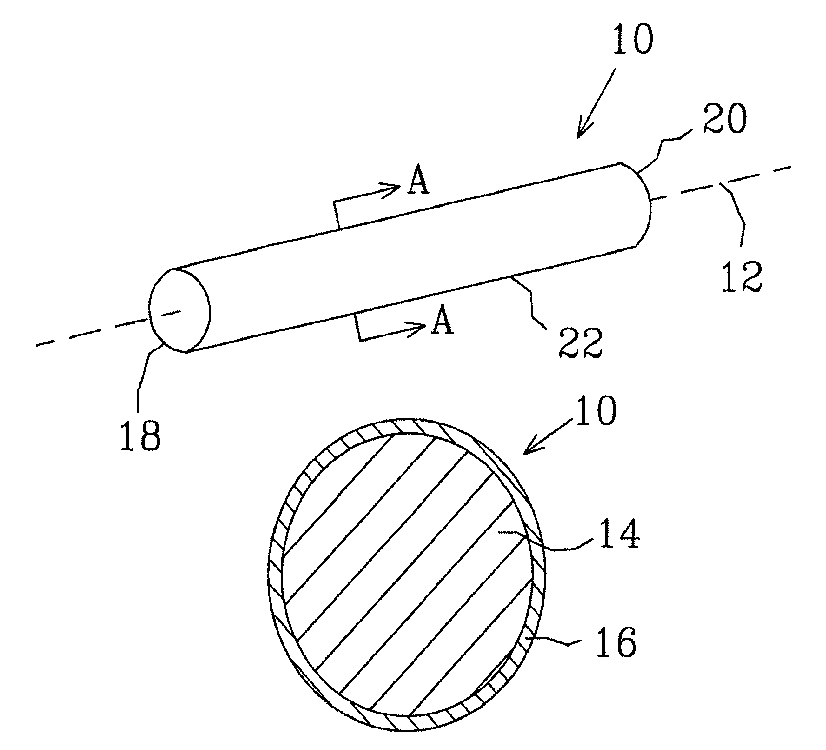
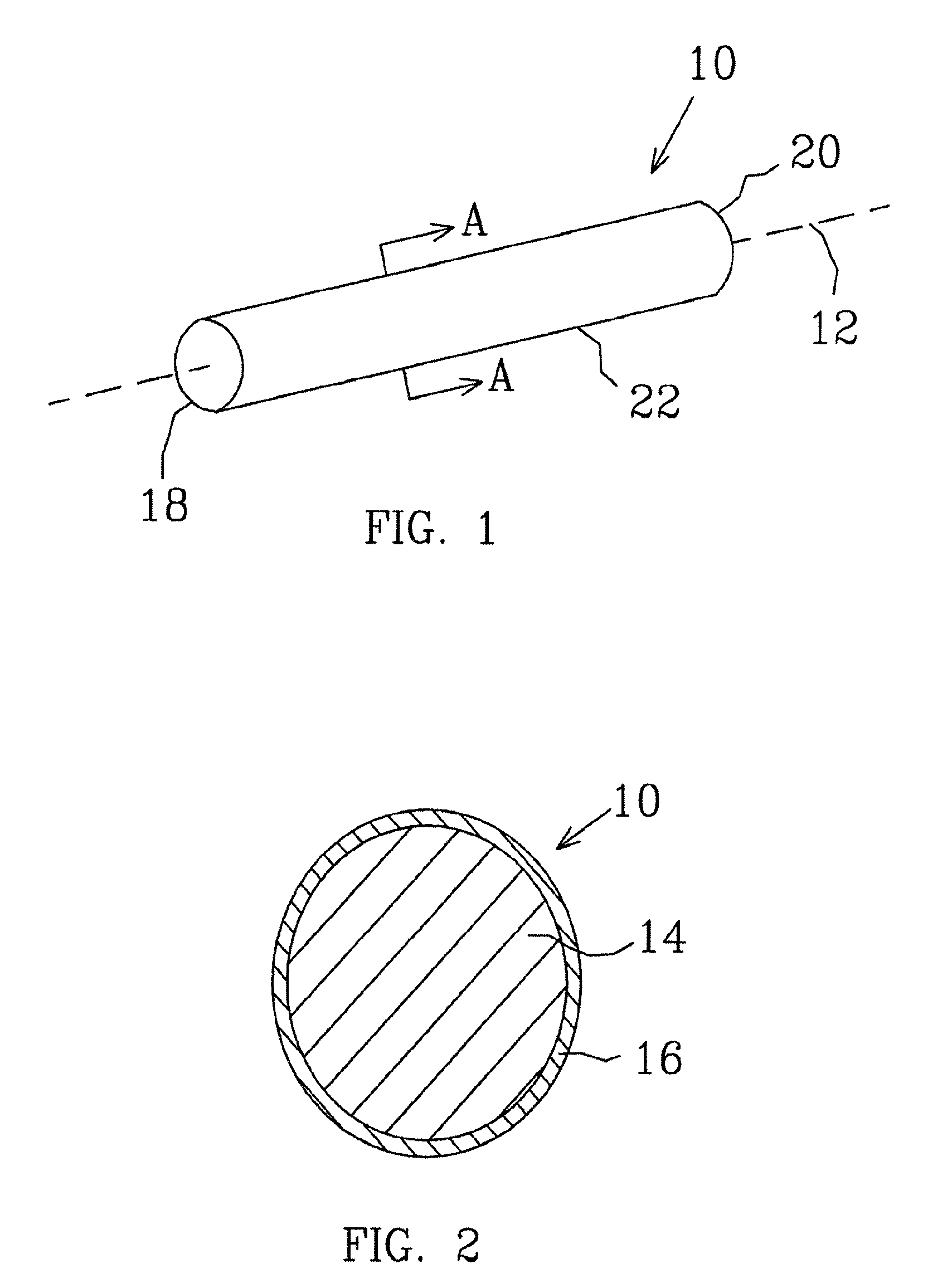
[0025]Referring now to FIG. 1, there is shown a perspective view of one embodiment of a reinforcement dowel according to the present invention. In this embodiment, dowel pin 10 comprises a cylindrically shaped bar covered by a sacrificial metal, as is described in further detail in association with FIG. 2. Dowel pin 10 has a longitudinal axis 12.

[0026]FIG. 2 shows a cross-sectional view of the reinforcement dowel of FIG. 1 at line A-A. Dowel pin 10 comprises bar 14 and sacrificial metal coating 16. In this embodiment, metal coating 16 covers all exposed surfaces of bar 14. Referring to FIG. 1, metal coating 16 covers first and second ends 18 and 20, respectively, and also covers longitudinal surface 22 about longitudinal axis 12. Bar 14 is comprised of steel, carbon steel, other ferrous metal, or other corrosive structural material. Metal coating 16 comprises zinc, zinc alloy, magnesium, magnesium alloy, aluminum, or aluminum alloy. An example of a zinc alloy is one comprising 85% z...


PUM

PropertyMeasurementUnit
internal dimensionaaaaaaaaaa
external dimension(saaaaaaaaaa
pressureaaaaaaaaaa

Abstract

Galvanically protected reinforcement dowel pins and methods of producing the same. In one embodiment, the reinforcement dowel pins comprise a bar or tube, the longitudinal exposed surfaces of which are covered by a heavy gauge of a sacrificial metal, such as zinc, zinc alloy, magnesium, magnesium alloy, aluminum, or aluminum alloy. The bar or tube comprises steel, carbon steel, or other ferrous metal. The heavy gauge of sacrificial metal is applied to the ferrous metal by various processes, such as roll bonding, lock seaming, welding, die casting, flame spraying, plasma spraying, dipping, sinking, and drawing. The resulting reinforcement dowel pins resist corrosion without sacrificing structural integrity, and are reasonable in materials and manufacturing costs. These dowel pins may be installed in adjacent concrete panels using conventional methods, and therefore do not introduce additional costs in installation.

Description

CROSS-REFERENCE TO RELATED APPLICATIONS[0001]This application is a continuation of application Ser. No. 10 / 855,536, filed May 27, 2004 now abandoned.BACKGROUND OF THE INVENTION[0002]This invention relates to reinforcement dowel pins, and, in particular, to reinforcement dowel pins used in concrete surface construction, and methods of making the same.[0003]Concrete highways and other concrete surfaces are often built in sections. Such sections are useful in controlling and addressing thermal expansion of the concrete surface and avoidance of the problems, such as cracking, that can occur when thermal expansion is not controlled. To accommodate for thermal expansion, joints are usually placed between adjacent panels to allow movement in the direction of the roadway between panels while maintaining the correct lateral and vertical locations of each panel to keep the road surface level and in place.[0004]Various types of construction have been used for “joining” these adjacent panels. T...

Claims


Application Information

Patent Timeline
Patent Type & Authority Patents(United States)
IPC IPC(8): E04C5/01E04C5/03E01C11/14F16B21/00
CPCE01C11/14Y10S411/902Y10T428/12799
Inventor MILLER, WESSCHENK, CHRISTOPHER P.TARRANT, DEREK
Owner ARTAZN LLC
Why Eureka
Try Eureka