Click-fit connector for armored cables

a technology of armored cables and connectors, which is applied in the direction of machine supports, coupling device connections, manufacturing tools, etc., can solve the problems of inconvenient installation of connectors, inconvenient installation of cable connectors, and inability to easily or conveniently access wiring boxes, so as to improve engagement and minimize the displacement of installed connectors

Inactive Publication Date: 2009-06-30
DUCRET LUCIEN
View PDF1 Cites 21 Cited by
  • Summary
  • Abstract
  • Description
  • Claims
  • Application Information

AI Technical Summary

Benefits of technology

[0009]In accordance with one aspect of the present disclosure, a click-fir connector is configured with a hollow body, and first and second resilient components coupled to the hollow body and operative to bias the hollow body against a wall of a wiring box in opposite directions. Upon pulling the disclosed click-fit connector through an opening, which is formed in a wall of wiring box, the first and second resilient components press against the opposite sides of the wall and prevent the installed connector from voluntary displacement relative to the box.
[0012]The second resilient element includes at least one, but preferably multiple radially spaced prongs biased towards and pressing against the outer side of the wall of the box. In the installed state of the connector, the lugs and prongs engage the opposite sides of the wall of the box and minimize displacement of the installed connector relative thereto.
[0013]In accordance with a further aspect of the disclosure, the first resilient element is provided with a pair of wings resiliently pressing against a cable upon inserting the latter into the body of the connector. The configuration of the wings helps improve engagement between the cable and connector and allows only rotational motion of these components relative to one another. The resiliency of the wings is essential to maintaining contact between the armored jacket of the inserted cable and connector which is necessary for reliable grounding of the cable.

Problems solved by technology

Typically used in a space-deficient environment associated with electrical wiring, wiring boxes may not be easily or conveniently accessed.
Hence mounting a cable connector traversed by an armored cable is usually an onerous and labor-intensive task.
However, in practice, the engagement between a connector and box is not reliable, and the installed cable often wobbles and slips out of engagement.
Furthermore, the known configuration of the click-fit connector does not provide reliable grounding of the installed cable.

Method used


Image

  • Click-fit connector for armored cables
  • Click-fit connector for armored cables

Examples


Embodiment Construction

[0023]Reference will now be made in detail to several embodiments of the invention that are illustrated in the accompanying drawings. Wherever possible, same or similar reference numerals are used in the drawings and the description to refer to the same or like parts or steps. The drawings are in simplified form and are not to precise scale. For purposes of convenience and clarity only, directional terms, such as top, bottom, up, down, over, above, and below may be used with respect to the drawings. These and similar directional terms should not be construed to limit the scope of the invention in any manner. The words “connect,”“couple,” and similar terms with their inflectional morphemes do not necessarily denote direct and immediate connections, but also include connections through mediate elements or devices.

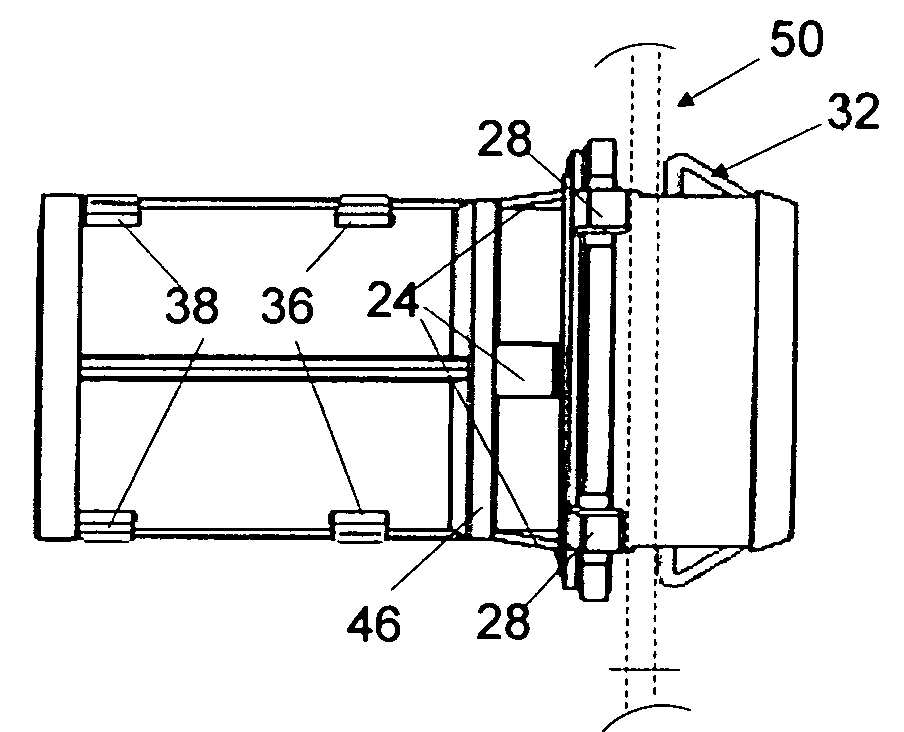
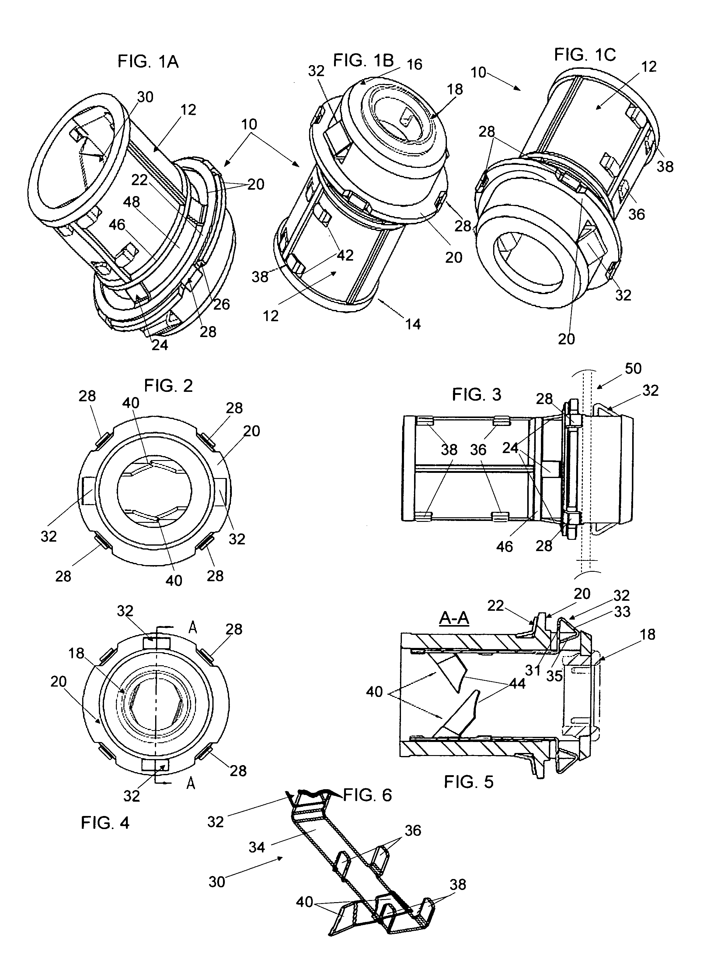
[0024]Referring now to FIGS. 1A, 1C and 3, a connector 10 is configured with a hollow body 12 traversed by an armored cable, such as XK-290 or BX which has a helical armored ...


PUM


Abstract

A connector for an armored cable mountable to a wiring box has a body provided with two biasing components which are operative to engage opposite sides of the wall of the wiring box and operative to maintain the desired position of the connector upon mounting its body to the box.

Description

BACKGROUND OF THE INVENTION[0001]1. Field of the Invention[0002]The invention relates to click-fit connectors for securely mounting armored cables to a cable connector box.[0003]2. Related Prior Art[0004]A connector for armored cables including, but not limited to BX and MC cables, is configured to be removably mounted to a wiring box. Typically used in a space-deficient environment associated with electrical wiring, wiring boxes may not be easily or conveniently accessed. The wiring box has typically a housing provided with a bottom, a peripheral wall extending from the bottom, and a lid removably topping the peripheral wall and closing the interior of the box. The peripheral wall typically has a plurality of openings shaped and dimensioned to receive respective cable connectors. Typically, a cable connector is configured with a hollow body traversed by a cable which is secured to the connector by screws or other types of fasteners. The connector itself is, in turn, coupled to a wi...

Claims


Application Information

Patent Timeline
Patent Type & Authority Patents(United States)
IPC IPC(8): H02G3/18
CPCH02G3/0691H02G15/007Y10T16/05
Inventor DUCRET, LUCIEN
Owner DUCRET LUCIEN
Why Eureka
Try Eureka