Tolerance ring for data storage with overlapping tab feature for mass control

a technology of tolerance rings and tabs, applied in couplings, elastic bearings, instruments, etc., can solve problems such as data loss, tribological failure of interfaces, damage to disks and heads, etc., and achieve the effect of maintaining mass eccentricity and reducing mass eccentricity

Active Publication Date: 2009-06-30
INTRL PLEX TECH INC
View PDF73 Cites 26 Cited by
  • Summary
  • Abstract
  • Description
  • Claims
  • Application Information

AI Technical Summary

Benefits of technology

[0016]In one embodiment, the tolerance ring reduces mass eccentricity by radially displacing the first tab to a second radius about the axis such that a radial gap is formed between the first tab and second tab. In another embodiment, the tolerance ring maintains mass eccentricity by overlapping the first tab with the second tab.

Problems solved by technology

Because there is relative motion between the disk surface and the magnetic head due to the disk rotation and head actuation, continuous contact between the head and disk can lead to tribological failure of the interface.
Such tribological failure, known colloquially as a “head crash,” can damage the disk and head, and usually cause data loss.
For example, the gap or spacing between the ends in prior art tolerance rings can cause mass imbalance thereby affecting the eccentricity and alignment of the actuator.
To compensate for mass imbalance, disk drive makers are forced to either manually align the gap in a direction known by trial and error to reduce mass imbalance (also referred to as clocking) or add overall eccentric mass which reduces performance.
Furthermore, minimizing the gap helps reduce mass imbalance but the tolerance ring ends are still rather long due to manufacturing constraints.

Method used


Image

  • Tolerance ring for data storage with overlapping tab feature for mass control
  • Tolerance ring for data storage with overlapping tab feature for mass control
  • Tolerance ring for data storage with overlapping tab feature for mass control

Examples


Embodiment Construction

[0027]Methods that implement the various features of the invention will now be described with reference to the drawings. The drawings and the associated descriptions are provided to illustrate embodiments of the invention and not to limit the scope of the invention. Reference in the specification to “one embodiment” or “an embodiment” is intended to indicate that a particular feature, structure, or characteristic described in connection with the embodiment is included in at least an embodiment of the invention. The appearances of the phrase “in one embodiment” or “an embodiment” in various places in the specification are not necessarily all referring to the same embodiment. Throughout the drawings, reference numbers are re-used to indicate correspondence between referenced elements. In addition, the first digit of each reference number indicates the figure in which the element first appears.

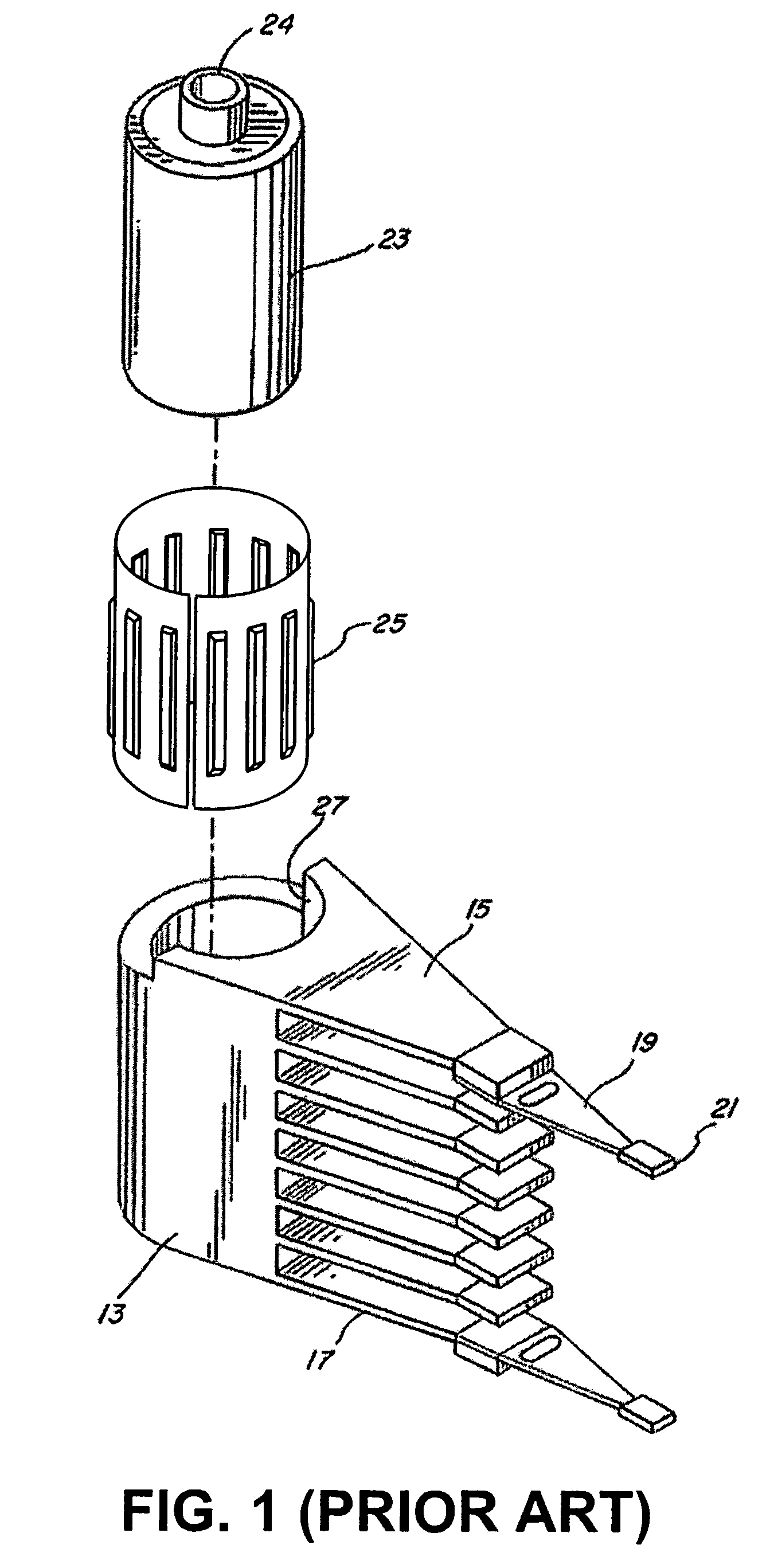
[0028]FIG. 1 is an exploded view of an actuator arm assembly 13 which includes a pivot bearin...


PUM

PropertyMeasurementUnit
lengthaaaaaaaaaa
radiusaaaaaaaaaa
axial lengthaaaaaaaaaa

Abstract

A tolerance ring for coupling an actuator arm to a pivot bearing while maintaining mass eccentricity of the actuator arm. The tolerance ring having a substantially cylindrical base portion with a first radius about a central axis and extending a length parallel to the central axis, the cylindrical base portion has a first tab and a second tab extending along the length of the cylindrical base portion, the first tab being positioned proximate to the second tab. The tolerance ring improves mass eccentricity by radially displacing the first tab at a second radius about the axis such that a radial gap is formed between the first tab and second tab.

Description

FIELD OF THE INVENTION[0001]This invention relates generally to tolerance rings used in connection with bearings. More particularly, the invention pertains to tolerance rings used between cartridge bearings and actuator arms in information storage devices.DESCRIPTION OF THE RELATED ART[0002]A key component of any computer system is a device to store data. One common place for storing massive amounts of data in a computer system is on a disc drive. The most basic parts of a disc drive are a disc that is rotated, an actuator that moves a transducer to various locations on the disc, and electrical circuitry that is used to write and read data to and from the disc. Coupled to the actuator is a head-gimbal assembly (HGA) that includes a head and metal suspension. The HGA's can be stacked together into a head-stack assembly (HSA), which is propelled across the disk surface by the actuator. There are a variety of disc drives in use today, such as hard disc drives, zip drives, floppy disc d...

Claims


Application Information

Patent Timeline
Patent Type & Authority Patents(United States)
IPC IPC(8): G11B5/55
CPCF16C27/00G11B5/4813F16C11/04F16C2370/12F16D1/0835
Inventor HANRAHAN, KEVIN P.SCHMIDT, RYAN J.DEXTER, DAVID D.
Owner INTRL PLEX TECH INC
Why Eureka
Try Eureka