
Simplicity sonic depth finder for fishing

a technology of depth finder and sonic, which is applied in the field of fishing detector, can solve the problems of complicated and inconvenient use of string for drawing out sinkers, too expensive detectors to use for fishing, and unfit leisure use of detectors

Inactive Publication Date: 2009-06-30
PHARMED MEDICARE PVT LTD
View PDF5 Cites 16 Cited by
  • Summary
  • Abstract
  • Description
  • Claims
  • Application Information

AI Technical Summary

Benefits of technology

[0038]To solve the above problems of the conventional art, it is an object of the present invention to provide an inexpensive fishing detector which can display detection results through a personal portable communications terminal which downloads several programs enabling detection for fishing, as well as which is integrated with a light-emitting indicator or a numerical indicator other than a wireless transmit / receive system.
[0039]It is another object of the present invention to provide a fishing detector which is light-emitted at a state where the detector hanging on a fishing rope is thrown to thereby enable a fisher to grasp distribution of fishes at a fishing site, and which enables the fisher to recognize a detail condition including the depth of water, the water temperature etc., through a predetermined switching after taking the detector out from the water.
[0040]In particular, it is still another object of the present invention to provide a fishing device which enables a fisher to confirm a detail condition including the depth of water, the water temperature etc., immediately after being put into an ice hole and then being taken out therefrom in the winter season.
[0041]It is yet another object of the present invention to provide a fishing detector which can display detection results through a personal portable communications terminal, as well as which enables a fisher to grasp the detection results through a light-emitting indicator or a numerical indicator.
[0042]It is still yet another object of the present invention to provide a fishing detector which enables a fisher to detect the depth of water, the water temperature, the fish distribution, etc., using a personal portable communications terminal such as a mobile phone, only with transmission and reception sound waves and wireless transmission and reception signals for transmitting the transmission and reception sound waves, in which light emitting elements are removed from the fishing detector.

Problems solved by technology

However, the detector is too expensive to use it for fishing.
It is also unfit to use the detector for leisure in view of its cost and place where it is used.
However, it is complicated and inconvenient to use a string for drawing out a sinker while maintaining a stabilized buoyancy between a sinker and a floater.
Further, the depth of water is measurable but the water temperature or the distribution range of the fishes cannot be measured.
However, such an underwater image acquisition device is relatively big in volume and expansive in price.
Thus, the underwater image acquisition device is being restrictively used only for the underwater photography, and has not been reasonable to be used as a leisure fishing device.
However, these are not also used as a simplified commercialized fishes locating device for leisure.
One of the key issue points of the detectors which are respectively attached on a fishing rod is caused by the length of a cable such as a fishing rope in which the distance throwing the fishing rope from the fishing rod is short.
The other problems include rapid power consumption, errors of a display device, intermittently ceased echo signals, and interference phenomena due to similar detectors which are being used in the same place by the other fishers.
Moreover, the detectors and the fishing ropes lengthily overhang between the float and the river embankment or seashore, to thus cause a complexity in the fishing site.
Further, the fishing rope may happen to be tangled with the transmission line for the sound detector, during a reeling.
Although a reeling is not performed, the fishing rope may be easily tangled with the transmission line for the sound detector when the fishing rope becomes tight or loose during fishing.
Further, since the underwater sound detector should consistently move between the screen and the float, the above-described problems may frequently occur.
However, the above-described fishing detector which are respectively disclosed in the U.S. patents, has caused the following defects in a wireless transmission and reception system between an underwater sonar detector and a wireless receiver secured in a wrist.
That is, when considering various kinds of applications of a personal portable communications terminal such as audio reception, MP3 playing, digital multimedia broadcasting (DMB) reception, and navigation for personal portable communications service, a separate wrist-secured type receiver may cause a burden which has to prepare for a separate dedicate receiver in addition to the already-available personal portable communications terminal.
As a result, this may also include the defectives that a new telecommunications device should be provided as the receiver as well as a unit cost problem.
However, these underwater fishing detectors are not applied to a personal communications terminal including a mobile telephone.
Thus, it is difficult or unreasonable to prepare for devices corresponding to all kinds of such wireless transmit / receive devices.

Method used


Image

  • Simplicity sonic depth finder for fishing
  • Simplicity sonic depth finder for fishing
  • Simplicity sonic depth finder for fishing

Examples


Embodiment Construction

[0072]A variety of detectors for fishing according to respective preferred embodiments of the present invention will be described with reference to the accompanying drawings.

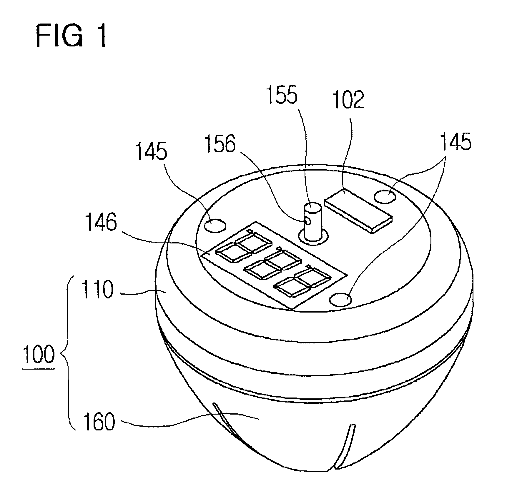
[0073]FIG. 1 is a perspective view showing an external appearance of a detector for fishing according to a first embodiment of the present invention.

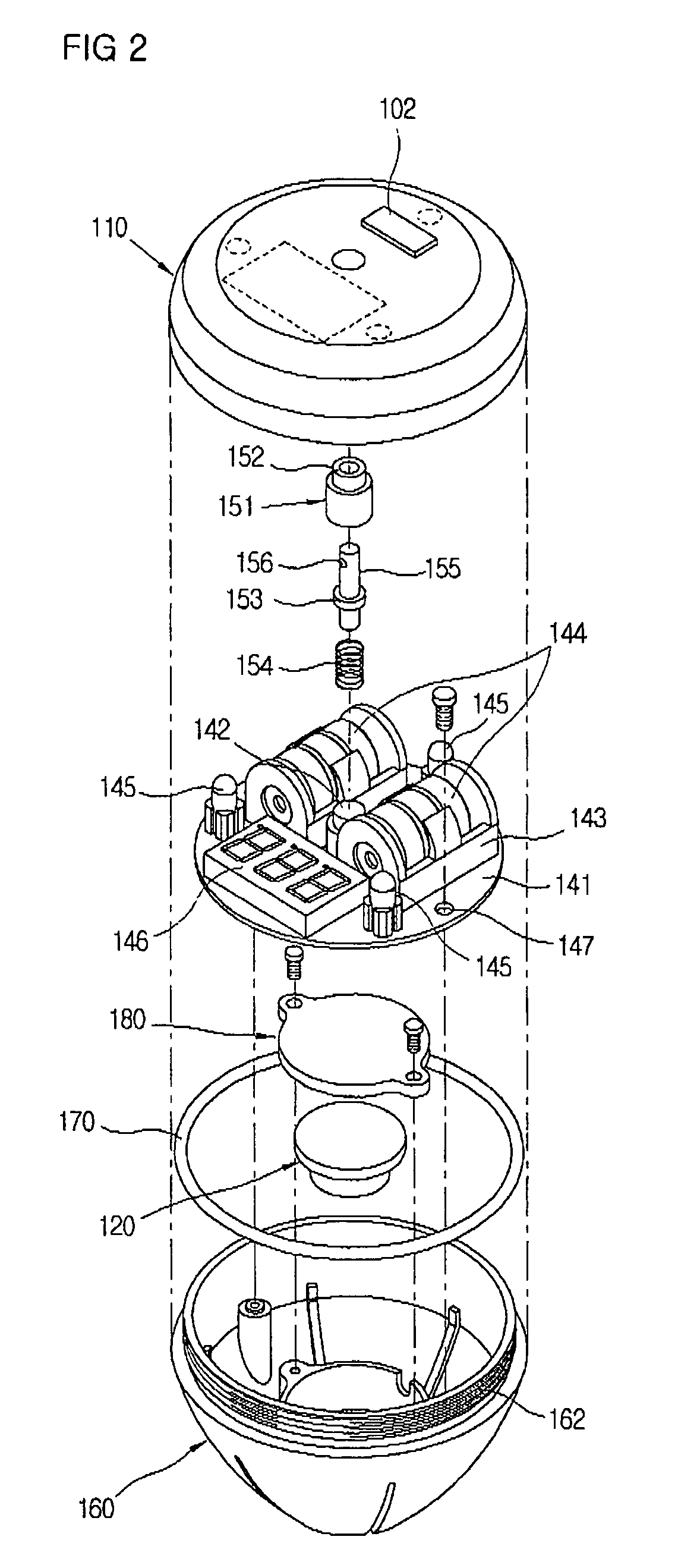
[0074]As shown in FIG. 1, a main body 100 of a fishing detector according to the present invention has an external appearance of a tumbler shape whose inner and outer portions have a water-tight structure in which an upper cover 110 and a lower cover 160 are assembled with screws. As will be described later, an O-ring 170 is interposed between the upper cover 110 and the lower cover 160 to thereby maintain water-tightness therebetween. An elevating rod 155 which includes an engagement hole 156 to be describes later is exposed at the center of the upper surface.

[0075]Three light-emission indicators 145, a numeric indicator 106, and a water depth / temperature indicator...


PUM


Abstract

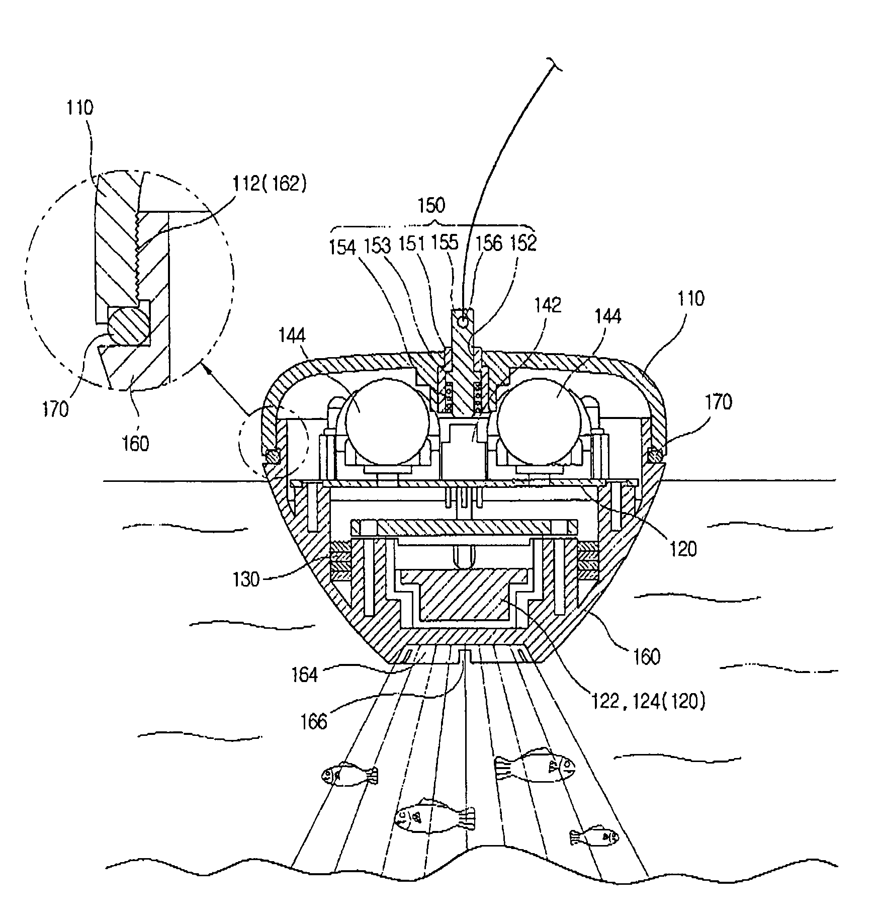
Provided is a detector for fishing in order to detect the depth of water, the temperature of water, the distribution of fishes including fishes' migration and / or the length of fishes. The detector includes: a sensor transmitting an ultrasonic signal into the water in a fishing site and receiving a reflective ultrasonic signal reflected from an underwater object; a control unit analyzing / determining the waveform of the reflective ultrasonic signal measured in the sensor to then be indicated on an indication unit including a light-emission indicator, a numeric indicator, and a water depth / temperature indicator; a switching unit having an elevating rod whose lower end contacts an activation switch to turn on / off electric power supplied from a power source and in the upper end of which a fishing line engagement hole is formed in which a fishing line is connected with the fishing line engagement hole and the elevating rod is exposed to the outside to then be elastically pressed to be opened and closed according to the pressure of the elevating rod; and a main body on the upper surface of which a light-emission indicator, a numeric indicator, and a water depth / temperature indicator are formed, and in which the sensor, the control unit, and the switching unit are embedded in a sealed manner with a predetermined structure. The detector further includes a transmitter transmitting a signal representing the analyzed / determined result in the form of a predetermined waveform wirelessly. The wireless signal transmitted from the transmitter in the fishing detector is received and displayed using a predetermined program via a predetermined receiver having a display such as a personal portable communications terminal like a mobile telephone.

Description

CROSS-REFERENCE TO RELATED PATENT APPLICATION[0001]This application claims the benefit of Korean Patent Application No. 00-2005-000000, filed on Nov. 4, 2005, in the Korean Intellectual Property Office, the disclosure of which is incorporated herein in its entirety by reference.BACKGROUND OF THE INVENTION[0002]1. Field of the Invention[0003]The present invention relates to a detector for fishing, and more particularly, to a fishing detector which detects the depth of water, the temperature of water, the distribution of fishes, and / or the length of fishes at a fishing spot, to thereby immediately indicate the detection results in various kinds of methods or display the detection result on a portable mobile communications terminal in order to represent a density of waveform corresponding to the detection results.[0004]2. Description of the Related Art[0005]Conventionally known detectors for detecting fishes, which are called sonar, are fishing-vessel dedicated devices. The detectors a...

Claims


Application Information

Patent Timeline
Patent Type & Authority Patents(United States)
IPC IPC(8): G01S15/96
CPCG01S7/521G01S15/96A01K97/00
Inventor PARK, KYO-YANG
Owner PHARMED MEDICARE PVT LTD
Learn More