
Activation unit for explosive masses or explosive bodies

a technology of activation unit and explosive body, which is applied in the direction of electric fuze, firework flare/torch, ammunition fuze, etc., can solve the problem that decoys of this kind cannot be used in civil aviation, and achieve the effect of simple design and safety requirements for decoys and dispensers without explosives, high temperature resistance, and high susceptibility to corrosion

Inactive Publication Date: 2014-05-06
RHEINMETALL WAFFE MUNITION GMBH
View PDF68 Cites 2 Cited by
  • Summary
  • Abstract
  • Description
  • Claims
  • Application Information

AI Technical Summary

Benefits of technology

The patent is about a new type of heating elements for use in decoys and dispensers without explosives. These elements have been designed to allow for extremely fast heating and dynamic adjustments, using small masses and highly temperature-resistant materials. The outer casing of the heating elements is composed of a highly temperature-resistant steel with a high CrNi content, and ceramic inlays minimize heat loss. The heating elements can also be equipped with contact plates for improved energy transfer. This thermal optimization results in a short reaction time of the heating elements, meaning the time from switch-on point to reaching the normal temperature is very short. The heating elements can be activated either by contact with the target or contactlessly, with the latter allowing for the use of decoys and dispensers without explosives in different civil environments. The design is safe and simplified compared to traditional flares, and the functional reliability can be improved through current sharing and clean routing of the explosive-body pack. Ignition over a large surface area is achieved with a low mass, minimal thermal inertia, and dynamic heating regulation.

Problems solved by technology

Decoys of this kind cannot be used in civil aviation because of the munition component since explosives are not acceptable in this context and international safety agreements, etc., have to be complied with.

Method used


Image

  • Activation unit for explosive masses or explosive bodies
  • Activation unit for explosive masses or explosive bodies
  • Activation unit for explosive masses or explosive bodies

Examples


Embodiment Construction

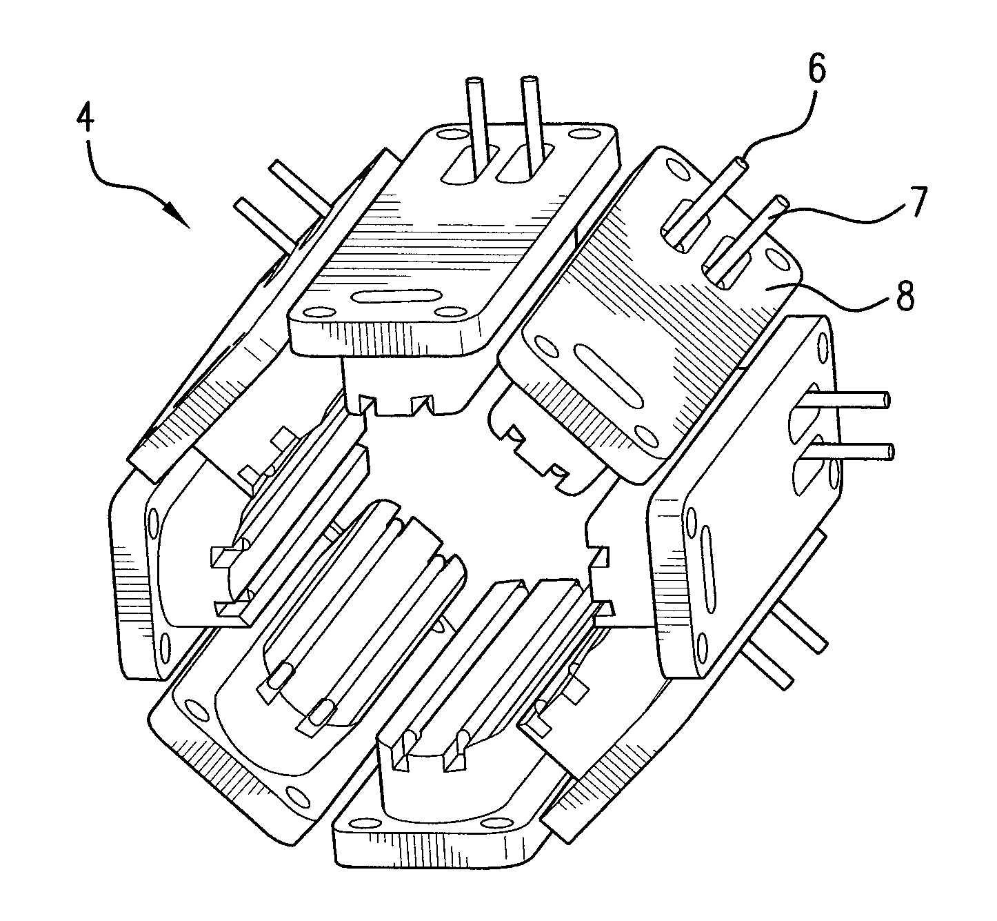
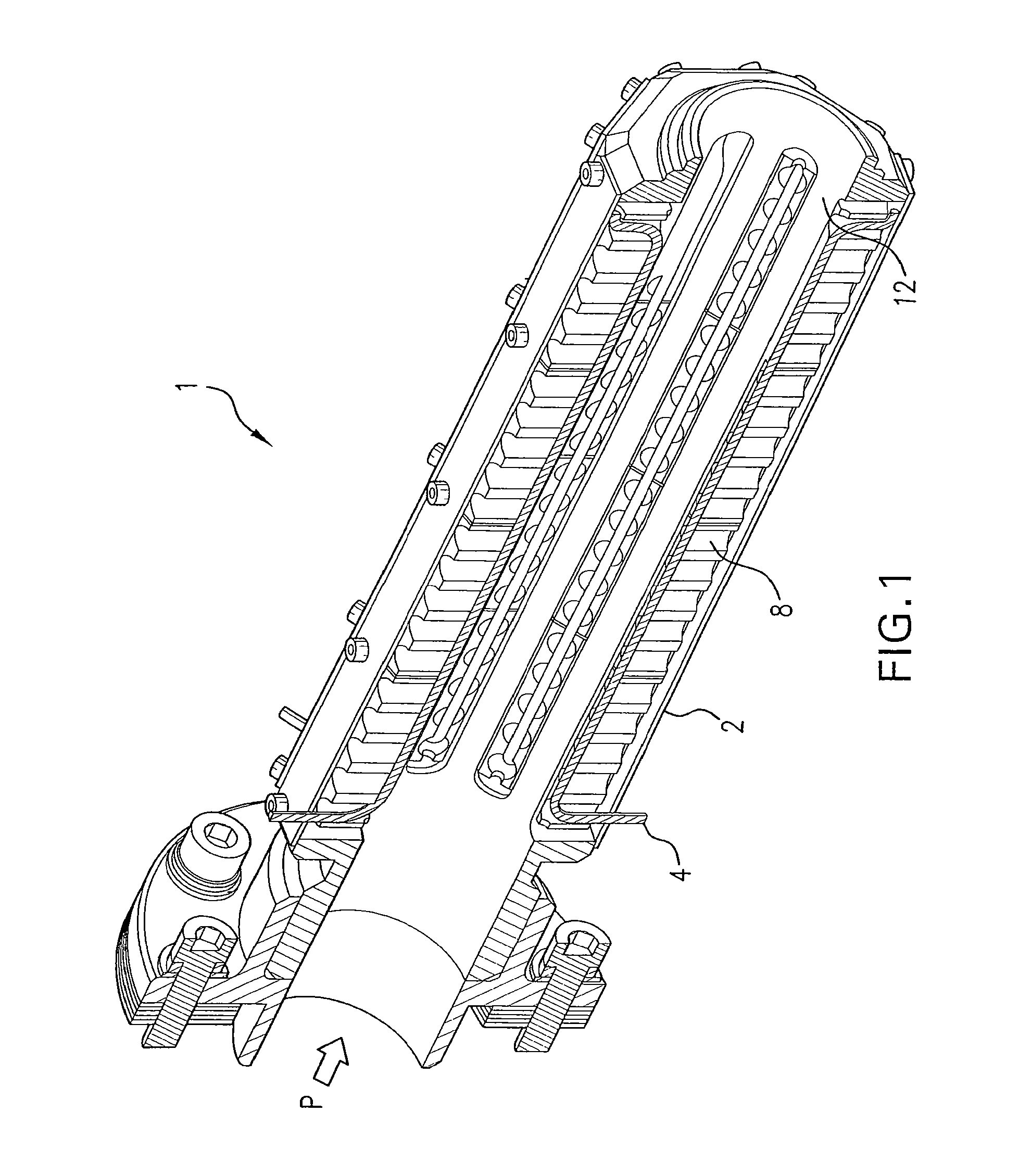
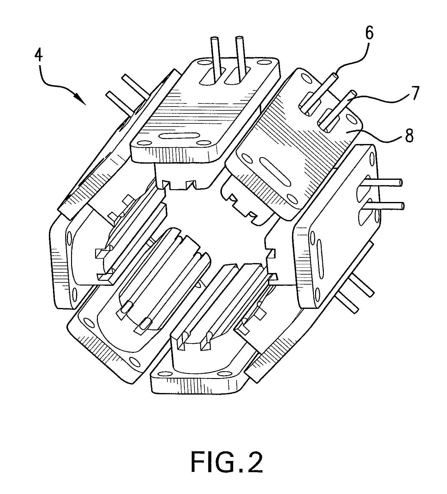
[0029]In the sectional view illustrated in FIG. 1, 1 denotes an activation unit. The high-temperature activation unit 1 substantially comprises an ejection tube 2 from which an explosive body 3 (FIG. 5), which is not illustrated in any more detail here, is ejected in the direction of the arrow P. The ejection tube 2 is surrounded by high-temperature heating elements 4 on its inner face / surface, with each individual element 4 being formed from a heating wire 6 that is held in a casing 7, protected against external influences, and is preferably embedded in a material that minimizes heat loss, preferably in a ceramic inlay 8. In the preferred embodiment, the outer casing 7 of the heating element 4 is composed of a highly temperature-resistant steel provided with a high CrNi content. For mechanical strain relief, the ceramics 8 are held in the metal structure of the ejection tube 2, with the metal structure corresponding to the external shape of the explosive body 3, in this case a cyli...


PUM


Abstract

An activation unit for explosive masses or explosive bodies includes an ejector tube and high-performance heating elements mounted around the ejector tube, each made of at least one heating wire supplied with electrical power by a control unit. Each heating wire is enclosed in a casing and embedded in a material minimizing heat loss. When the explosive body is passed through the activation unit, the jacket surface of the explosive body contacts the individual elements of the activation unit in a direct or non-contact manner. Thermal energy is transferred to the explosive body by means of the heating wires, and the body ignites at the contact points. A further activation unit includes heating elements in the ejector tube, at least partially fed longitudinally through the ejector tube, made of heating wire clad with CrNi steel and contact plates soldered thereto.

Description

[0001]This is a Continuation-in-Part Application in the United States of International Patent Application No. PCT / EP2010 / 002332 filed Apr. 16, 2010, which claims priority on German Patent Application No. 10 2009 020 558.6, filed May 8, 2009, and on German Patent Application No. 10 2009 020 557.8, filed on May 8, 2009. The entire disclosures of the above patent applications are hereby incorporated by reference.FIELD OF THE INVENTION[0002]The invention relates to an activation unit for, in particular, munition-free explosive masses or explosive bodies, for example, for forming decoys.BACKGROUND OF THE INVENTION[0003]Decoys and / or smoke shells based, for example, on red phosphorus (RP) or nitrocellulose (NC), are used in military applications, for example, smoke shells, infrared (IR)-acting aircraft decoys, etc. The smoke or IR effect is deployed by the RP / NC after appropriate ignition by burning. RP units (i.e., explosive bodies) are ignited via an ignition or break-up charge, which e...

Claims


Application Information

Patent Timeline
Patent Type & Authority Patents(United States)
IPC IPC(8): F42B3/12F42B3/10
CPCF42B5/145F42B3/10F42B4/26F42B3/12F42B5/155F42B5/15F42C11/001F41J2/02
Inventor PRELIC, NENANDFRANK, OLIVEREGLAUER, HERIBERTHUBER, FLORIAN
Owner RHEINMETALL WAFFE MUNITION GMBH
Learn More