Wireless communication terminal and wireless communication method

a wireless communication and terminal technology, applied in the field of wireless communication terminals and wireless communication methods, can solve the problems of patent document 1 not being applied in wireless data communication with a server, requires an extremely takes a long time to reconnect, so as to reduce the time required for reconnection. the effect of load on the user

Inactive Publication Date: 2009-06-30
KYOCERA CORP
View PDF18 Cites 2 Cited by
  • Summary
  • Abstract
  • Description
  • Claims
  • Application Information

AI Technical Summary

Benefits of technology

[0017](1) To reduce the load placed on the user by a reconnection process when the wireless communication terminal receives a communication connection error from the server; and
[0018](2) To reduce the time required by the reconnection process when the wireless communication terminal receives a communication connection error from the server.
[0023]According to the invention, when performing wireless data communication with a server connected to a network, the load placed on the user in performing a reconnection process when the wireless communication terminal receives a communication connection error from the server can be reduced, and the time required to perform the reconnection process can be shortened.

Problems solved by technology

However, since the wireless communication terminal is in a non-communicable state, the TCP disconnection message it generates does not reach the server, and the TCP connection established on the server side continues.
However, since a TCP connection using the above communication port number is already established on the server side, the TCP connection state on the wireless communication terminal side does not match that on the server side.
After disconnecting the PPP, the wireless communication terminal displays an error message on a self-contained display unit such as a liquid crystal panel, thereby notifying the user that a communication connection error with the server has occurred.
Thus when the server transmits an RST packet during the TCP connection process, the wireless communication terminal requires an extremely long time to reconnect since it is performing a series of processes that includes disconnecting the TCP, disconnecting the PPP, displaying an error to the user, and restarting the PPP connection if the user issues a reconnection command.
When the power of the data receiver is turned OFF during data communication with the FTP server, the FTP server treats this as an error in the communication port number on the data receiver side.
Consequently, when the data receiver performs a process of establishing communication connection with the FTP server after the power is turned ON again, since it is conventional to use the same communication port number as that used in the previous communication, the FTP server determines that there is an error in the communication port number on the data receiver side, and transmits an error message to the data receiver.
Consequently, it takes a long time to reconnect.
Therefore, Patent Document 1 cannot be applied in wireless data communication with a server.
Furthermore, when the server determines that there is an error in the communication port number on the wireless communication terminal side as described above, the wireless communication terminal requires a longer time to reconnect than in wired data communication since it performs the series of processes that includes disconnecting the TCP, disconnecting the PPP, displaying the error to the user, and restarting the PPP connection if the user issues a reconnection command.
There is also a considerable load on the user, since he must determine whether to reconnect to the server and input a command indicating his decision.

Method used


Image

  • Wireless communication terminal and wireless communication method
  • Wireless communication terminal and wireless communication method
  • Wireless communication terminal and wireless communication method

Examples


Embodiment Construction

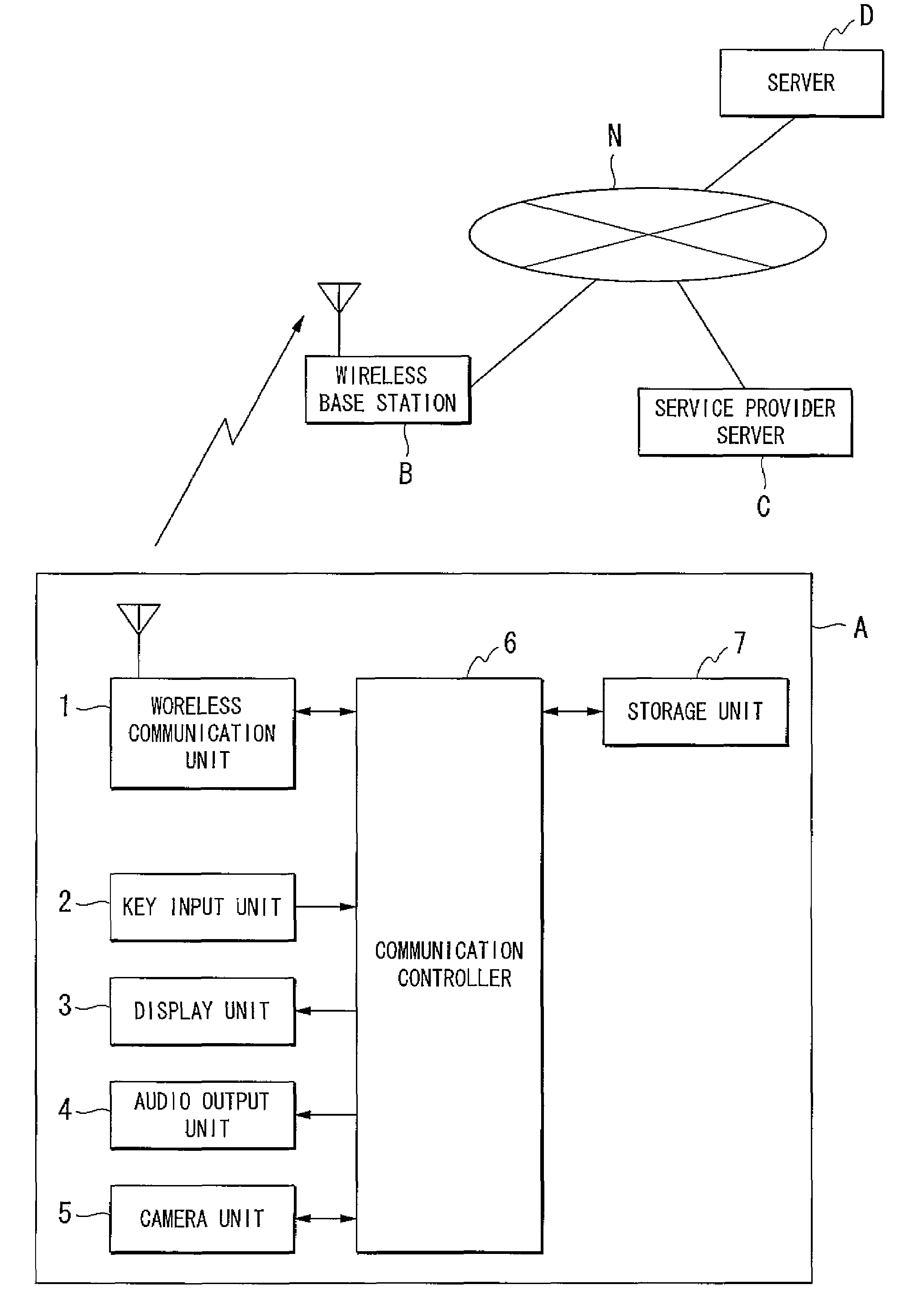
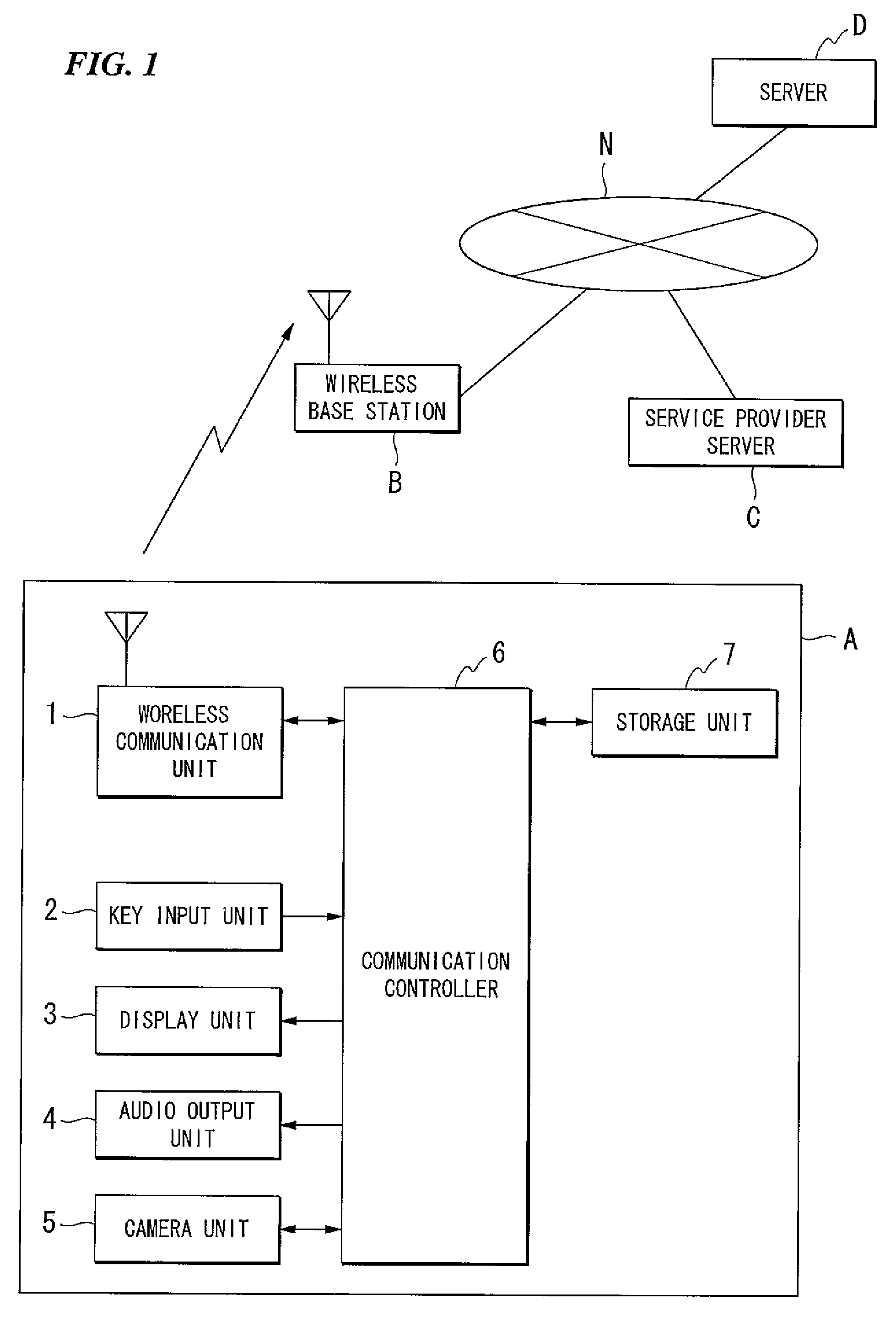
[0026]An embodiment of the invention will be explained with reference to the drawings. FIG. 1 is a configuration block diagram of a wireless communication terminal according to an embodiment of the invention. A mobile telephone is described as an example of a wireless communication terminal. As shown in FIG. 1, a wireless communication terminal A includes a wireless communication unit 1, a key input unit 2, a display unit 3, an audio output unit 4, a camera unit 5, a communication controller 6, and a storage unit 7. In FIG. 1, reference code B represents a wireless base station, C represents a service provider server, D represents a server, and N represents a network.

[0027]In the wireless communication terminal A, the wireless communication unit 1 performs wireless communication with the wireless base station B using a predetermined communication method such as code division multiple access (CDMA), and also performs data communication with the service provider server C and the serve...


PUM


Abstract

A wireless communication terminal has a function of performing data communication with a server connected to a network, and includes a communication controller which selects a predetermined port number from among a plurality of port numbers allocated for data communication with the server, and using this communication port number to perform data communication with the server, and a storage unit which stores the communication port number; while performing a process to establish a communication connection with the server, if the communication controller receives information indicating that communication connection is impossible from the server, it selects a port number which is different from the communication port number stored in the storage unit as a new communication port number, and performs the process again.

Description

BACKGROUND OF THE INVENTION[0001]1. Field of the Invention[0002]The present invention relates to a wireless communication terminal and a wireless communication method.[0003]Priority is claimed on Japanese Patent Application No. 2005-285227, filed Sep. 29, 2005, the content of which is incorporated herein by reference.[0004]2. Description of Related Art[0005]A wireless communication terminal such as a mobile telephone including a function of communicating data with a server connected to a network generally establishes communication with the server by the following processing procedure. When the wireless communication terminal receives a command to start data communication with the server from a user (actually, when the user presses a special key for starting data communication on the wireless communication terminal), it starts a point to point protocol (PPP) connection process and obtains an internet protocol (IP) address from a service provider. After establishing the PPP connection...

Claims


Application Information

Patent Timeline
Patent Type & Authority Patents(United States)
IPC IPC(8): H04L12/66H04J1/16H04W88/02G06F13/00H04L12/70H04L29/08
CPCH04W76/027H04W40/00H04W76/18
Inventor SHIBASAKI, TOSHIYUKI
Owner KYOCERA CORP
Why Eureka
Try Eureka