
Media foundation media processor

a processor and multimedia technology, applied in the field of computing, can solve problems such as problems such as troublesome shutting down of a given filter, unanticipated problems caused by filter use, and large number of api's for filter entry, and achieve the effect of efficient processing of multimedia streams

Active Publication Date: 2009-06-30
MICROSOFT TECH LICENSING LLC
View PDF12 Cites 18 Cited by
  • Summary
  • Abstract
  • Description
  • Claims
  • Application Information

AI Technical Summary

Benefits of technology

This approach enables efficient processing of multimedia streams by centralizing communication and control, reducing the complexity of software design, and enhancing the stability and performance of multimedia applications by decoupling control and data handling, thus addressing the limitations of the DirectShow architecture.

Problems solved by technology

While filters allowed a great deal of reuse of programs, the use of filters also created some unanticipated problems.
One of the problems created by filters is the large number of API's for the filters which came into being.
Also, the use of filters creates the problem of shutting down a given filter problematic.
In general, programming a filter to gracefully handle the loss of an interface is difficult, as the state of the filter can be unknown when the interface is lost.
The loss of interfaces, therefore, tends to lead to unpredicted behavior in the filters and ultimately to ill behaved programs.
Distributing the control in this manner makes software design cumbersome as there are inevitably some control functions which cross the boundary between the blocks.
Another problem with DirectShow is that the filters shoulder the responsibility of media format negotiation and buffer management functionality.
The dependency on filters causes applications building on DirectShow susceptible to bugs and inefficiencies that could be programmed into a filter.
Thus, a badly written filter could easily bring down the filter graph and an application associated with the filter graph.

Method used


Image

  • Media foundation media processor
  • Media foundation media processor
  • Media foundation media processor

Examples


Embodiment Construction

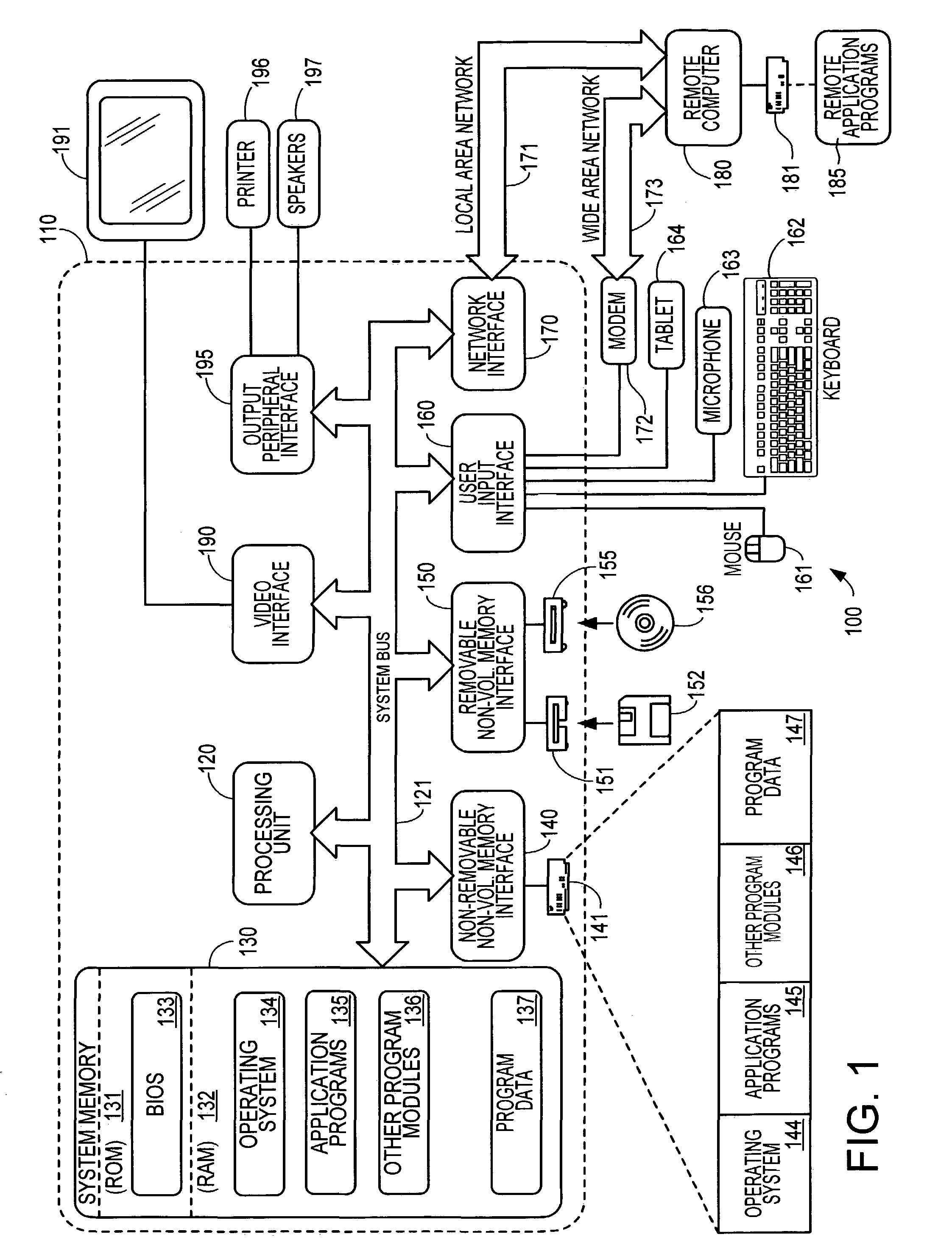
[0017]Turning to FIG. 1, an exemplary computing device 100 on which the invention may be implemented is shown. The computing device 100 is only one example of a suitable computing device and is not intended to suggest any limitation as to the scope of use or functionality of the invention. For example, the exemplary computing device 100 is not equivalent to any of the computing devices 10-17 illustrated in FIG. 1. The exemplary computing device 100 can implement one or more of the computing devices 10-17, such as through memory partitions, virtual machines, or similar programming techniques, allowing one physical computing structure to perform the actions described below as attributed to multiple structures.

[0018]The invention may be described in the general context of computer-executable instructions, such as program modules, being executed by a computer. Generally, program modules include routines, programs, objects, components, data structures, etc. that perform particular tasks ...


PUM


Abstract

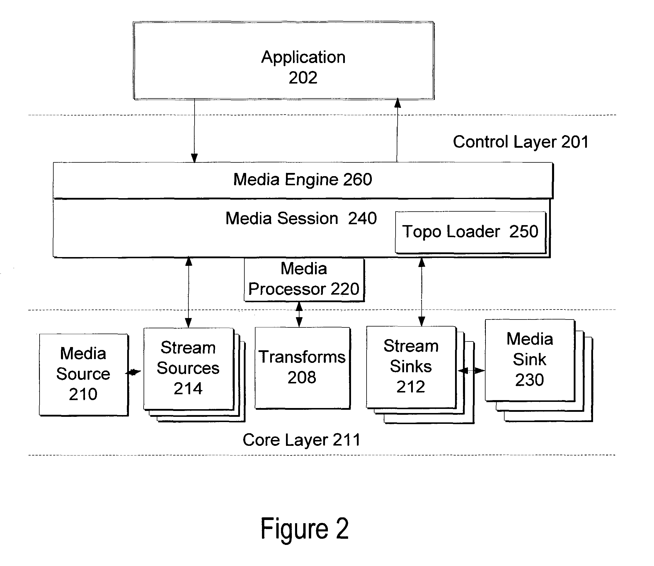
A system and method for a media processor separates the functions of topology creation and maintenance from the functions of processing data through a topology. The system includes a control layer including a topology generating element to generate a topology describing a set of input multimedia streams, one or more sources for the input multimedia streams, a sequence of operations to perform on the multimedia data, and a set of output multimedia streams, and a media processor to govern the passing of the multimedia data as described in the topology and govern the performance of the sequence of multimedia operations on the multimedia data to create the set of output multimedia streams. The core layer includes the input media streams, the sources for the input multimedia streams, one or more transforms to operate on the multimedia data, stream sinks, and media sinks to provide the set of output multimedia streams.

Description

TECHNICAL FIELD[0001]This invention relates generally to computing and, more particularly, relates to handling multimedia data in a computing environment.BACKGROUND OF THE INVENTION[0002]As the abilities of computers expand into entertainment genres that once required separate electronic components, increased efficiency and user-friendliness is desirable. One solution is Microsoft's® DirectShow®, which provides playback of multimedia streams from local files or Internet servers, capture of multimedia streams from devices, and format conversion of multimedia streams. DirectShow® enables playback of video and audio content of file types such as Windows Media Audio, Windows Media Video, MPEG, Apple® QuickTime®, Audio-Video Interleaved (AVI), and WAV. DirectShow® includes a system of pluggable filter components. Filters are objects that support DirectShow® interfaces and can operate on streams of data by reading, copying, modifying and writing data to a file. The basic types of filters ...

Claims


Application Information

Patent Timeline
Patent Type & Authority Patents(United States)
IPC IPC(8): G06F15/173G06F7/00G06F9/04G06F15/16G06F15/163G06F17/00G06F17/30H04L7/10
CPCG11B27/034G11B27/34G11B2220/2562G11B2220/40G06F15/163H04L7/10
Inventor DUNBAR, GEOFFREY T.RUDOLPH, ERICMOHAMMED, SOHAIL BAIG
Owner MICROSOFT TECH LICENSING LLC
Learn More