Vehicle mounted with electric storage apparatus

a technology of electric storage and vehicle, which is applied in the direction of electric energy management, gas pressure propulsion mounting, propulsion parts, etc., can solve the problems of affecting taking up a lot of cooling space, so as to reduce the space necessary for cooling space and improve the layout freedom of peripheral parts

Inactive Publication Date: 2009-07-07
HONDA MOTOR CO LTD
View PDF17 Cites 14 Cited by
  • Summary
  • Abstract
  • Description
  • Claims
  • Application Information

AI Technical Summary

Benefits of technology

[0007]It is an object of the present invention is to provide a vehicle mounted with an electric storage apparatus in which an energy storage unit as well as a drive unit can be cooled, with a layout freedom of peripheral parts being improved by reducing a space necessary for cooling.

Problems solved by technology

As a result, it takes much space for cooling, and can affect a layout freedom of peripheral parts.

Method used


Image

  • Vehicle mounted with electric storage apparatus
  • Vehicle mounted with electric storage apparatus
  • Vehicle mounted with electric storage apparatus

Examples


Embodiment Construction

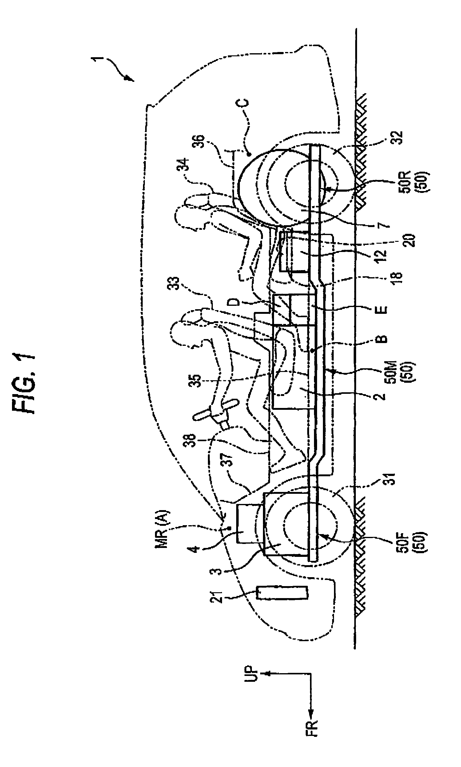
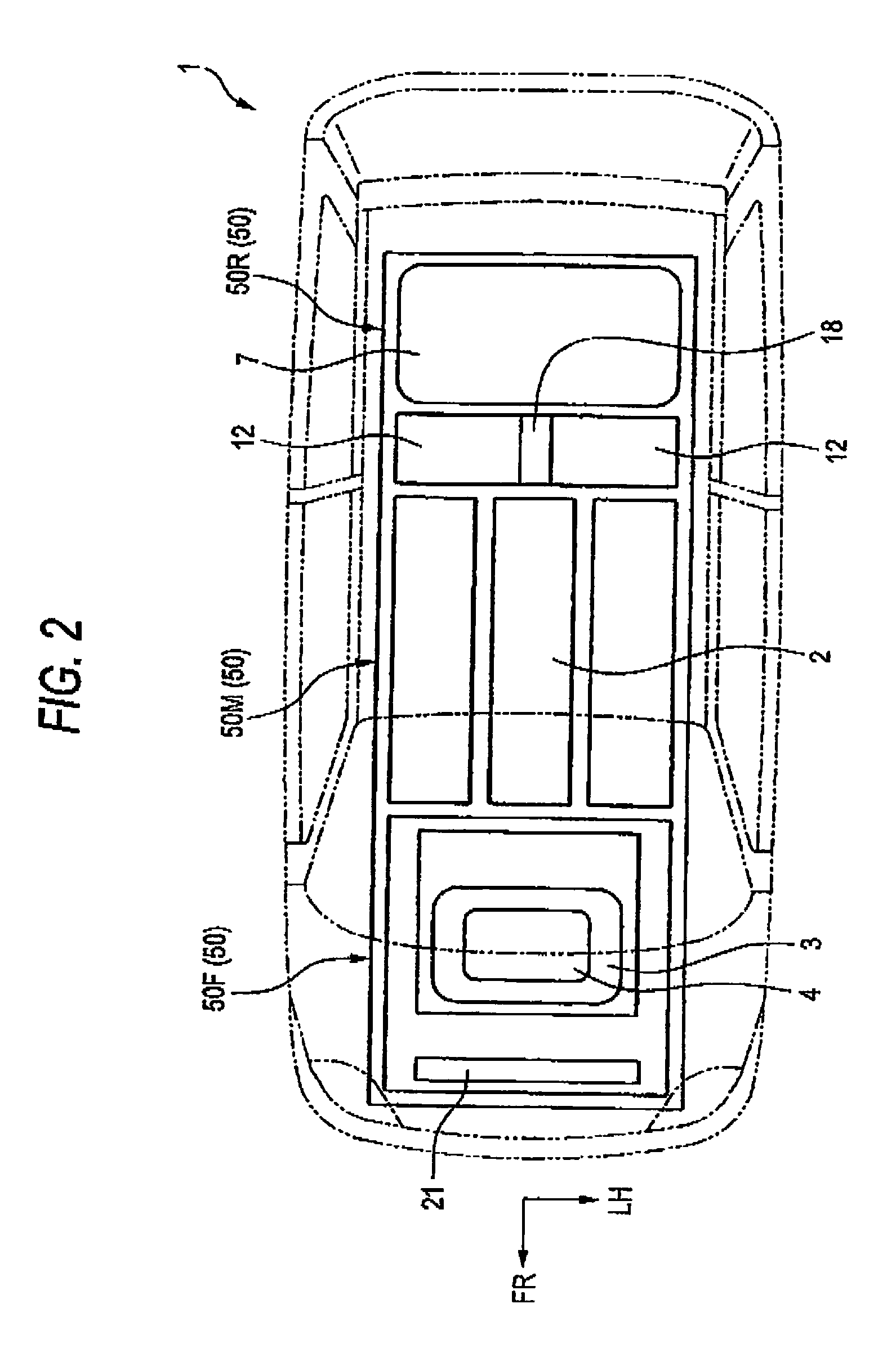
[0016]The invention will be described below with reference to the drawings. In the following description, directions of front, rear, left and right are the same as those in a vehicle as long as there is no particular description. Further, in the drawings, an arrow FR indicates a forward direction of vehicle, an arrow LH indicates a leftward direction of vehicle, and an arrow UP indicates an upward direction of vehicle.

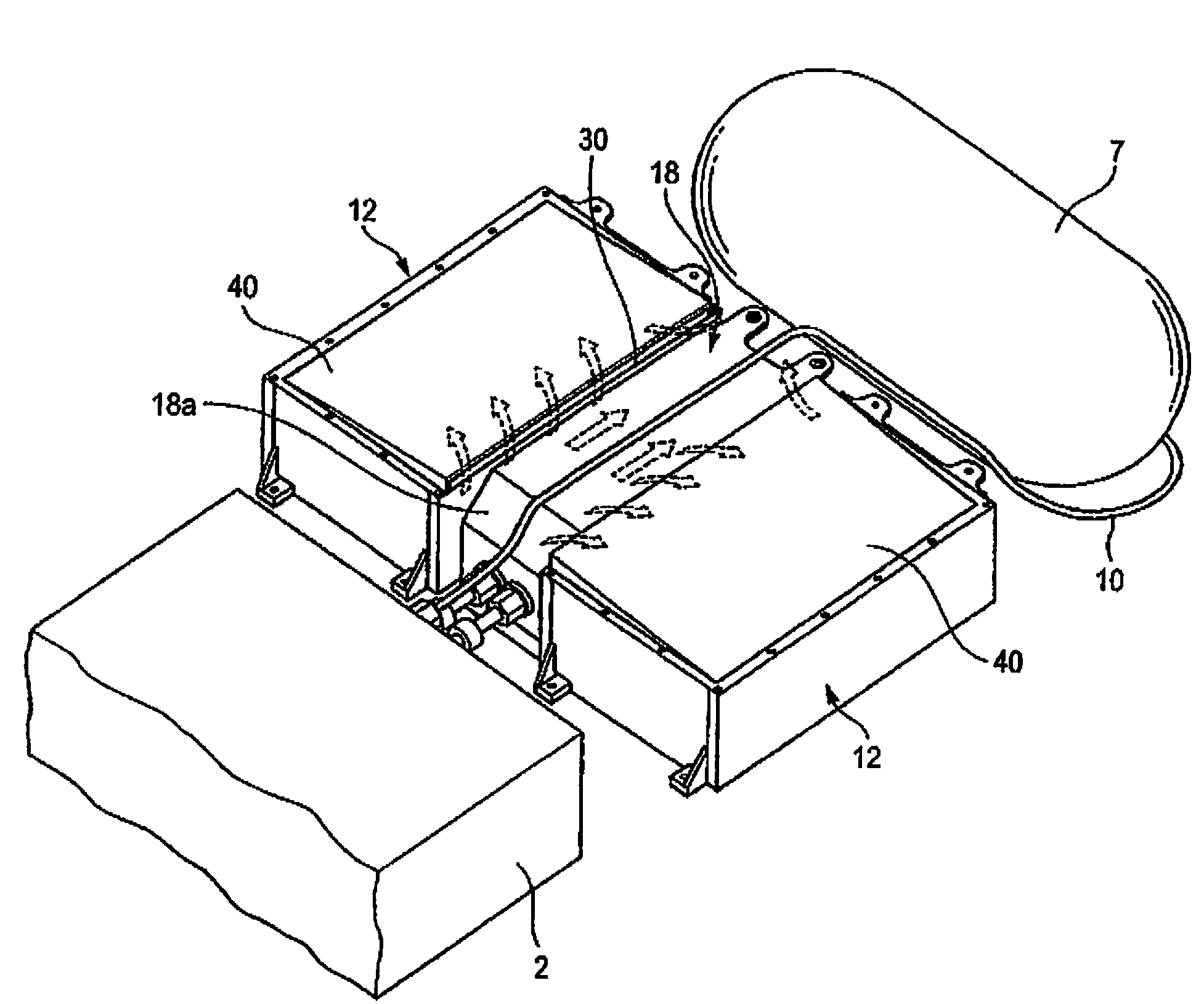
[0017]A fuel cell vehicle 1 shown in FIGS. 1 and 2 has a fuel cell stack (hereinafter sometimes simply referred to as a fuel cell), which generates electricity by electrochemical reaction between hydrogen and oxygen, below a floor of the vehicle, and runs by driving a drive motor 3 with electric power generated in the fuel cell stack 2. The fuel cell stack 2 is known as polymer electrolyte membrane fuel cell (PEMFC) in which many unit fuel cells (unit cells) are stacked. Hydrogen gas as a fuel gas is supplied to an anode side of the fuel cell stack 2, and air including...


PUM

PropertyMeasurementUnit
voltageaaaaaaaaaa
heightaaaaaaaaaa
lengthaaaaaaaaaa

Abstract

At least two or more energy storage units are disposed on the right and left sides, in a traveling direction, of a vehicle, and a drive unit for controlling these energy storage units is located between the two or more energy storage units. The drive unit is lower in height than the two or more energy storage units, whereby air passage are formed above the drive unit and between the two or more energy storage units.

Description

[0001]The present invention claims foreign priority from Japanese patent application no 2005-275645, filed on Sep. 22, 2005, the content of which is incorporated herein by reference.BACKGROUND OF THE INVENTION[0002]1. Field of the Invention[0003]The present invention relates to a vehicle mounted with an electric storage apparatus, the vehicle including an energy storage unit which can store electric energy, and a drive unit which controls the energy storage.[0004]2. Description of the Related Art[0005]Japanese Patent Unexamined Publication JP-A-2003-291655, for example, discloses a vehicle mounted with an electric-storage apparatus in which an energy storage unit (secondary battery in this case) can be cooled by providing a cooling air introducing duct on a hydrogen storage tank side, and introducing air, which is cooled by latent heat when hydrogen is emitted from the hydrogen storage tank, as secondary battery cooling air.[0006]Such vehicle provided with an energy storage unit has...

Claims


Application Information

Patent Timeline
Patent Type & Authority Patents(United States)
IPC IPC(8): B60R16/00B60K1/04B60K6/28B60K6/32B60K6/40B60K8/00B60K11/04B60K11/06B60K15/03H01M8/00H01M8/04
CPCB60K1/04B60L1/003B60L7/14B60L11/1803B60L11/1853B60L11/1864B60L11/1874B60L11/1887B60L11/1894B60L11/1896B60L11/1898H01M8/04007H01M8/04201H01M16/006B60K15/07Y02T10/7061B60K2001/003B60K2001/005B60K2015/0638B60L2210/12B60L2240/12H01M2008/1095Y02T90/34Y02E60/50Y02T10/7233B60L50/51B60L50/71B60L50/72B60L58/18B60L58/21B60L58/26B60L58/34B60L58/40Y02E60/10Y02T10/70Y02T10/72Y02T90/40
Inventor YAMAMOTO, AKIOMATSUNAGA, MINORUYAMAMOTO, KOICHIMATSUTANI, MASAHIROMATSUMOTO, MITSUNORI
Owner HONDA MOTOR CO LTD
Why Eureka
Try Eureka