Electromagnetic exciter

a technology of exciters and exciters, applied in the direction of dynamo-electric components, mechanical vibration separation, dynamo-electric machines, etc., can solve the problems of separation between printed wiring boards and frames, achieving size and cost reduction of devices,

Inactive Publication Date: 2009-07-07
CITIZEN ELECTRONICS CO LTD
View PDF15 Cites 9 Cited by
  • Summary
  • Abstract
  • Description
  • Claims
  • Application Information

AI Technical Summary

Benefits of technology

[0025]With the above-described arrangement, by controlling the caulking force applied from the caulking portion of the protector to thereby control the pressing force applied to the annular support member from the caulking portion through the printed wiring board, it is possible to adjust the force with which the outer ring portion of the second suspension is restrained or held by the annular support member, and hence possible to adjust the vibration resonance frequency of the magnetic circuit assembly.

Problems solved by technology

Incorporating both a speaker and a vibration-generating device into such a communications device, however, is disadvantageous from the viewpoint of achieving size and cost reduction of the device.
This may result in separation between the printed wiring board and the frame (i.e. the cylindrical side wall portion of the first suspension)

Method used


Image

  • Electromagnetic exciter
  • Electromagnetic exciter
  • Electromagnetic exciter

Examples


Embodiment Construction

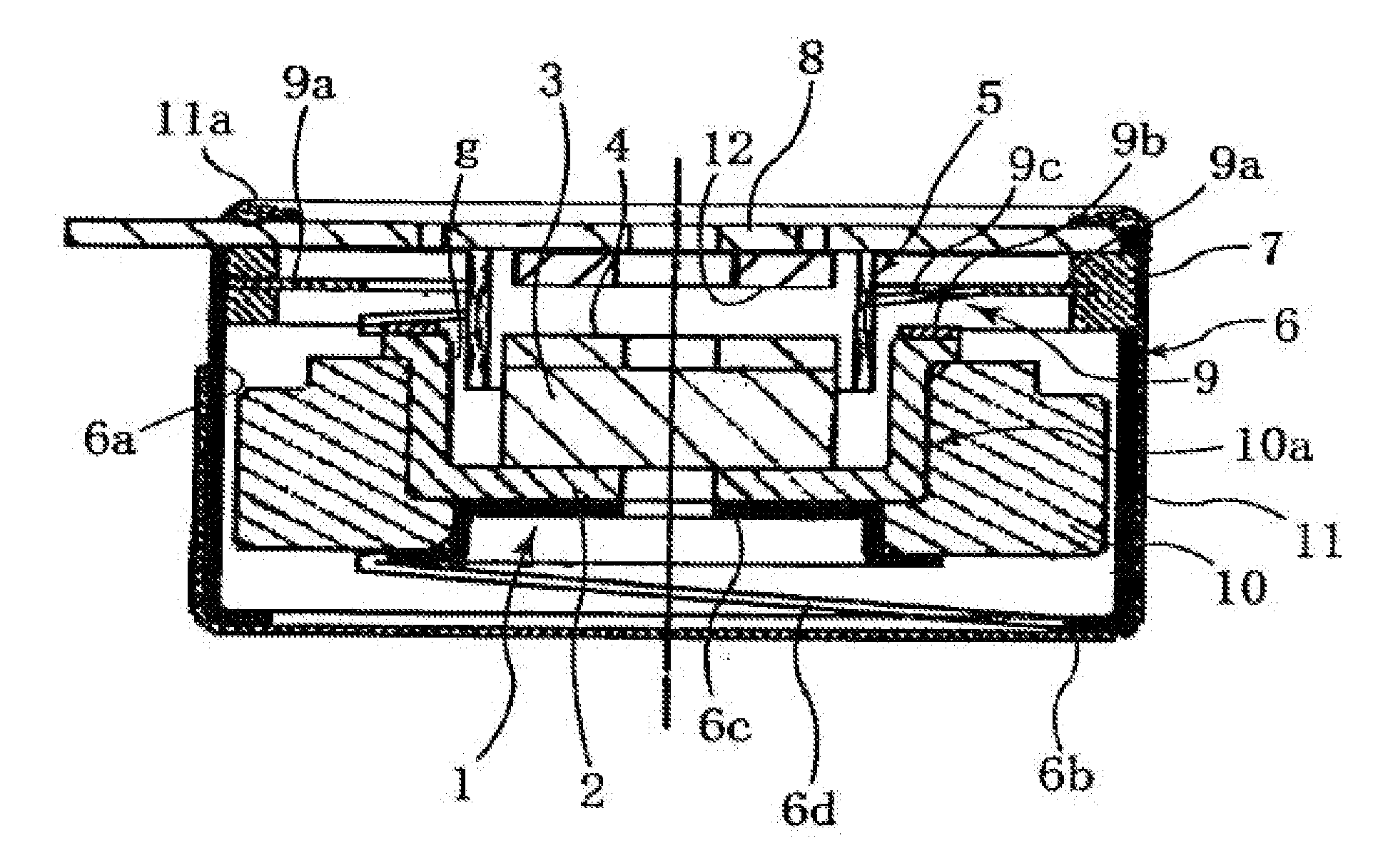
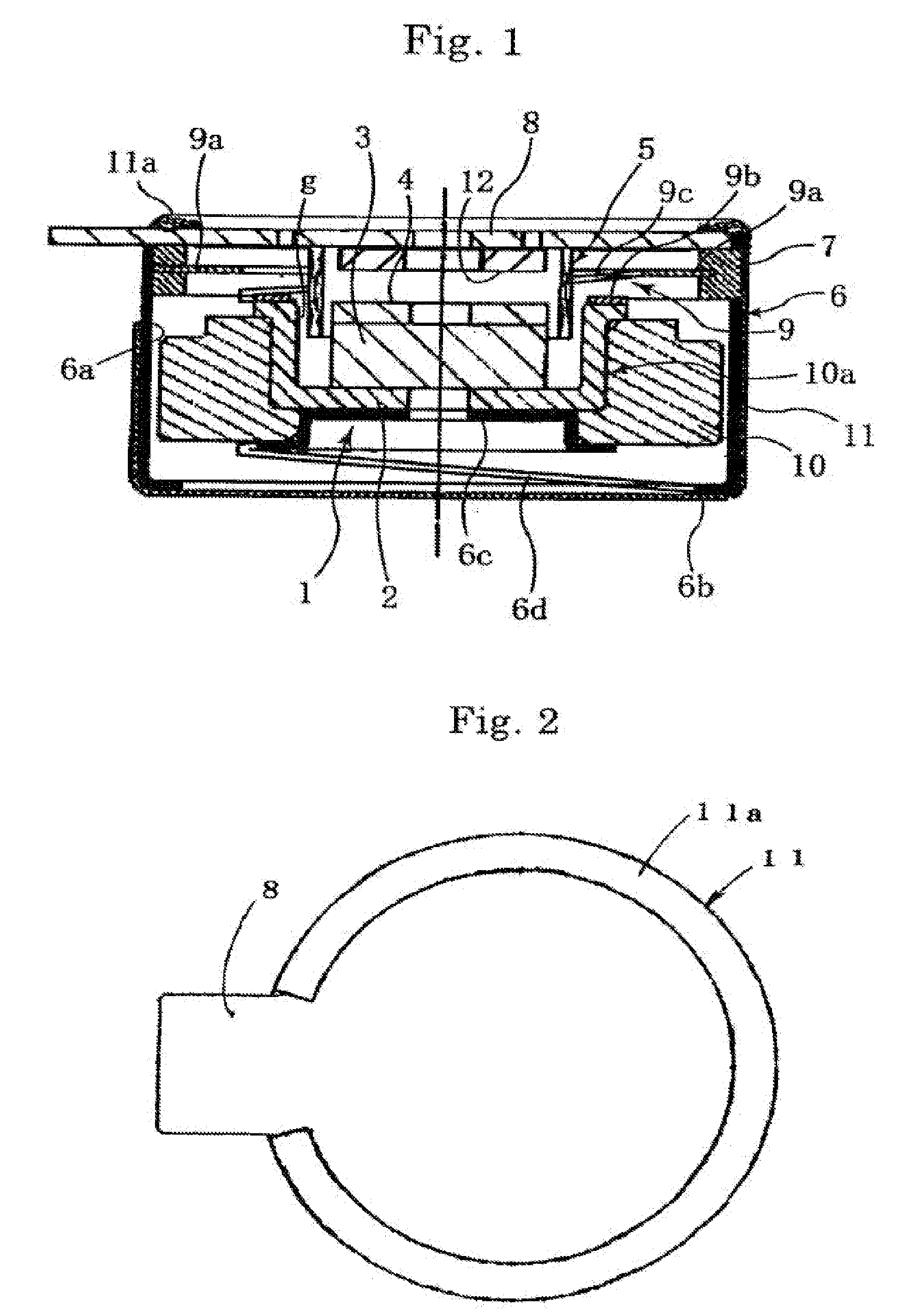
[0035]An embodiment of the electromagnetic exciter according to the present invention will be described below in detail with reference to FIGS. 1 to 3.

[0036]The electromagnetic exciter according to the embodiment of the present invention has a magnetic circuit assembly 1 including a substantially cup-shaped yoke 2 and a combination of a flat plate-shaped magnet 3 and a top plate 4 that are successively stacked in the yoke 2, and a voice coil 5 which is inserted in a gap (magnetic gap) g formed between the inner peripheral surface of the yoke 2 and the outer peripheral surface of the top plate 4. The electromagnetic exciter further has a weight 10 secured to the outer peripheral surface of the yoke 2.

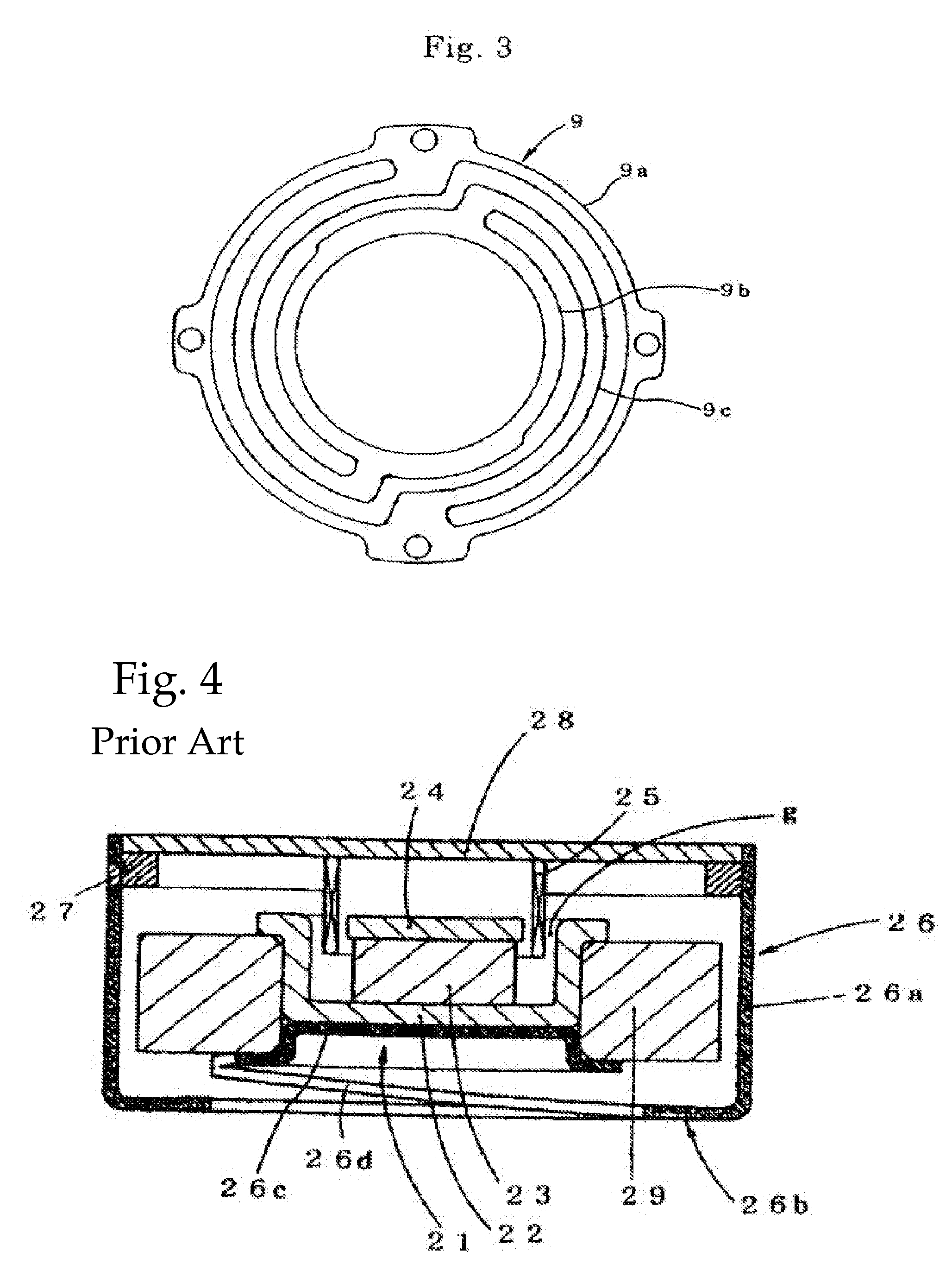
[0037]The magnetic circuit assembly 1 is supported by first and second suspensions 6 and 9 similar to those shown in FIG. 5.

[0038]More specifically, the first suspension 6 has a cylindrical side wall portion 6a, a ring portion 6b formed along the bottom edge of the cylindrical side wall ...


PUM


Abstract

An electromagnetic exciter includes a first suspension having a cylindrical side wall portion coaxial with respect to a cylindrical wall of a yoke of a magnetic circuit assembly, and a spring portion integrally formed at the lower end of the cylindrical side wall portion to support the lower end of the magnetic circuit assembly so that the magnetic circuit assembly is vibratable. An annular support member is secured to the inner peripheral surface of the upper end opening of the cylindrical side wall portion of the first suspension. A printed wiring board that supports a voice coil is supported on the annular support member. A protector has a cylindrical portion installed to cover the outer peripheral surface of the cylindrical side wall portion of the first suspension, and a caulking portion that is bent radially inward over the upper end edge of the cylindrical side wall portion of the first suspension to clamp the printed wiring board between itself and the annular support member.

Description

[0001]This application claims priority under 35 U.S.C. §119 to Japanese Patent Application No. JP2006-011087 filed Jan. 19, 2006, the entire content of which is hereby incorporated by reference.BACKGROUND OF THE INVENTION[0002]1. Field of the Invention[0003]The present invention relates to electromagnetic exciters that may be incorporated into mobile communications devices such as cellular phones and personal digital assistants (PDAs) to inform the user of an incoming call by vibrating a panel or a housing of a phone, for example.[0004]2. Description of the Background Art[0005]Conventionally, mobile communications devices such as cellular phones and personal digital assistants are arranged to inform the user of an incoming call by selectively generating beep sound or melody sound, or vibrating the housing of the device instead of producing sound. For this purpose, these communications devices incorporate a combination of a speaker for generating sound and a vibration-generating devi...

Claims


Application Information

Patent Timeline
Patent Type & Authority Patents(United States)
IPC IPC(8): H04R9/02H02K33/00
CPCB06B1/045H02K33/18H02K33/16
Inventor KUWABARA, ATSUSHIITAKURA, TOSHIO
Owner CITIZEN ELECTRONICS CO LTD
Why Eureka
Try Eureka