Magnetic/piezoelectric broadband vibration energy collector
A vibration energy harvesting, piezoelectric transducer technology, applied in generators/motors, piezoelectric effect/electrostrictive or magnetostrictive motors, electrical components, etc. Short and other problems, to achieve the effect of improving conversion efficiency, improving frequency response bandwidth, and good linearity
- Summary
- Abstract
- Description
- Claims
- Application Information
AI Technical Summary
Problems solved by technology
Method used
Image
Examples
Embodiment approach 1
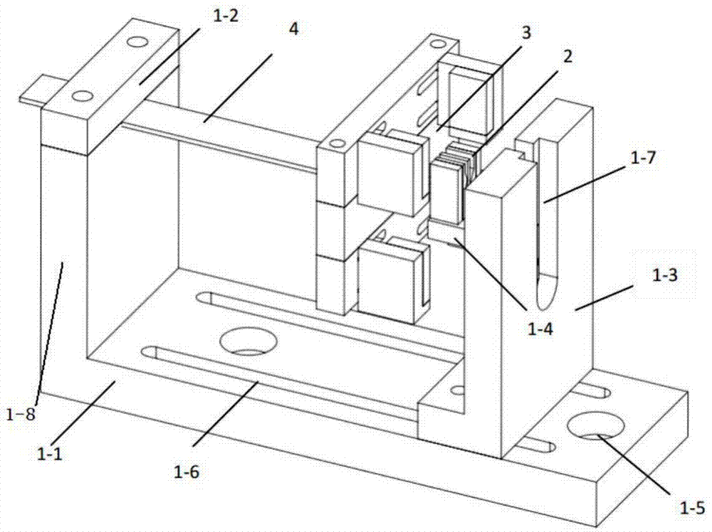
[0037] Such as figure 2 As shown: the magnetic circuit mechanism 3 and the cantilever beam 4 are connected into one body to form the main vibration mechanism, and the cantilever beam 4 is fastened to the bracket I1-8 with fastening strips 1-2, and the magnet / piezoelectric transducer 2 Place it on the drag table 1-4, adjust the height of the drag table 1-4 and the position of the magnetic circuit drag table 3-2, so that the magnet / piezoelectric transducer 2 is in the geometric center of the air gap of the magnetic circuit mechanism 3, and the overall force is applied balance. Specifically, the length of the cantilever beam 4 is adjusted so that the frequency of the main vibration mechanism during vibration is similar to the frequency of external vibration, so that its resonance can achieve the best output effect. When the energy harvester feels the vibration in the external environment and the magnet / piezoelectric transducer 2 is relatively displaced, a changed external magne...
Embodiment approach 2
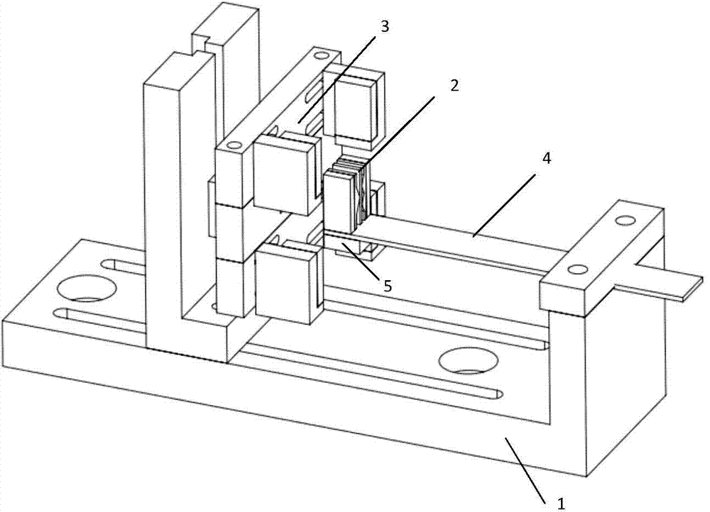
[0039] Such as figure 1 As shown: the magnet / piezoelectric transducer 2 and the cantilever beam 4 (plus mass) together form the main vibration mechanism, which is fastened on the support I1-8. According to the vibration characteristics in the environment, the length of the cantilever beam 4 and the weight of the mass block 5 are adjusted to achieve resonance, that is, the output reaches the maximum value. The magnetic circuit is symmetrically placed on the drag table 1-4, and the bracket II 1-3 is adjusted so that the magnet / piezoelectric transducer 2 can be at the geometric center of the air gap of the magnetic circuit mechanism 3, so that the magnet / piezoelectric transducer 2 is in static state force balance. The mechanical-magnetic-electrical conversion principle of the second scheme is the same as that of the first scheme, except that the main vibration structure becomes the magnet / piezoelectric transducer 2 and the cantilever beam 4 .
Embodiment approach 3
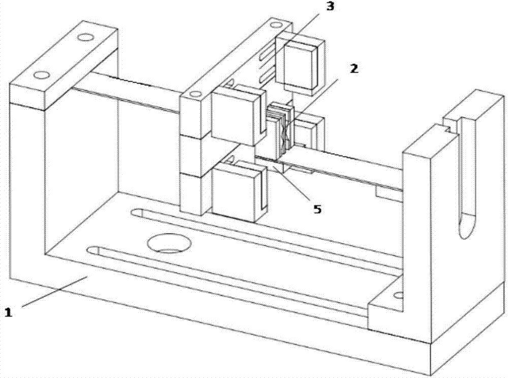
[0041] Such as image 3 As shown: the magnet / piezoelectric transducer 2 and the cantilever beam, the magnetic circuit mechanism 3 and the cantilever beam together form the main vibration mechanism, forming a transducer with a double-arm structure. The conversion principle of Scheme 3 is the integration of Scheme 1 and Scheme 2. When external vibration is excited, the transducer with double-arm structure has the adaptability to the environmental vibration frequency, which further improves the frequency response bandwidth of the transducer.
[0042] In the present invention, the gap between the magnetic circuit and the transducer can be adjusted according to the strength of the vibration in the environment so as to achieve the best output effect. The resonance frequency of the energy harvester is adjustable, and the length of the cantilever beam and the weight of the mass block can be changed to be similar to the frequency of external vibration, so that the resonance can achieve...
PUM
 Abstract
Description
Claims
Application Information
 - R&D
- Intellectual Property
- Life Sciences
- Materials
- Tech Scout
- Unparalleled Data Quality
- Higher Quality Content
- 60% Fewer Hallucinations
Browse by: Latest US Patents, China's latest patents, Technical Efficacy Thesaurus, Application Domain, Technology Topic, Popular Technical Reports.
© 2025 PatSnap. All rights reserved.Legal|Privacy policy|Modern Slavery Act Transparency Statement|Sitemap|About US| Contact US: help@patsnap.com


