Load/unload-type head suspension and method of processing the same
a head suspension and type technology, applied in the field of load/unload type head suspension, can solve the problems of reducing the recording capacity, the css area is not usable as a recording area, etc., and achieves the effect of smooth loading and unloading
- Summary
- Abstract
- Description
- Claims
- Application Information
AI Technical Summary
Benefits of technology
Problems solved by technology
Method used
Image
Examples
first embodiment
[0051]Head Suspension
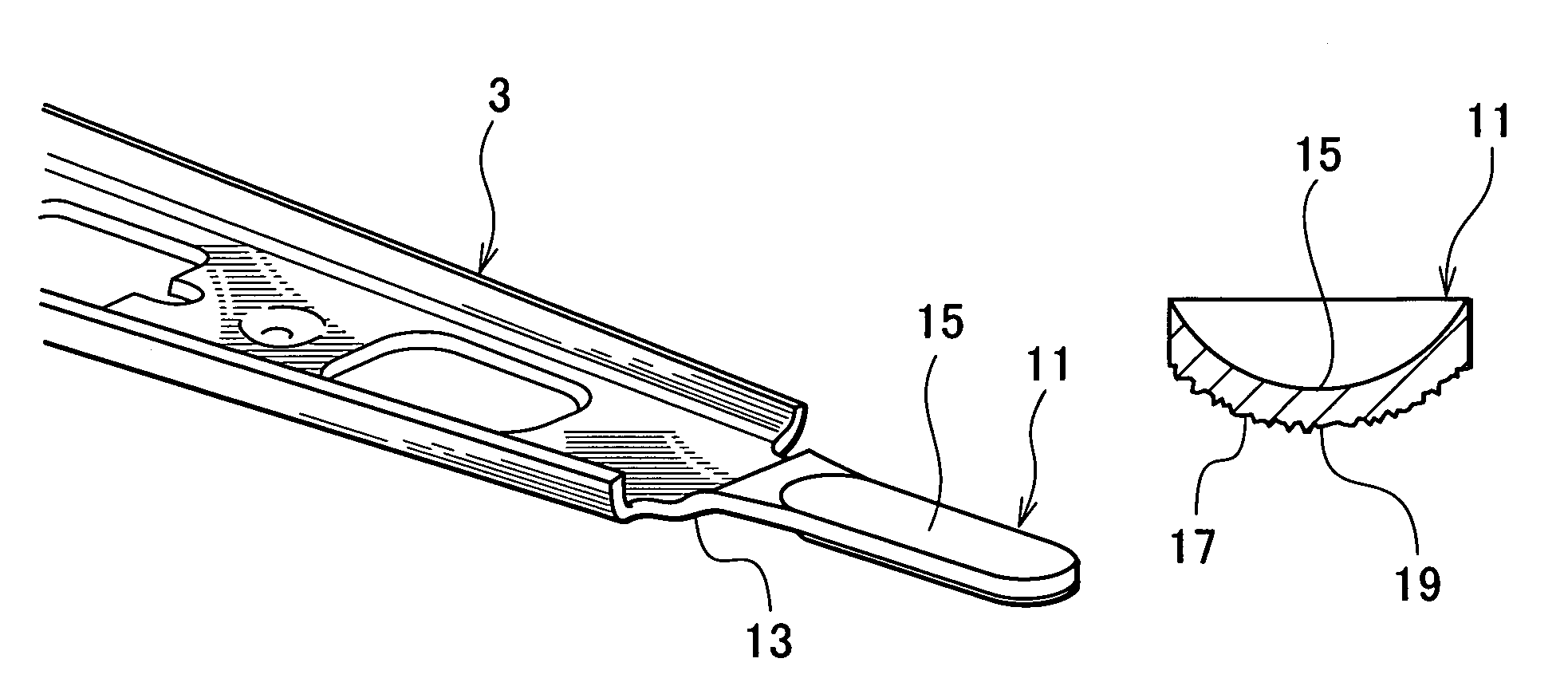
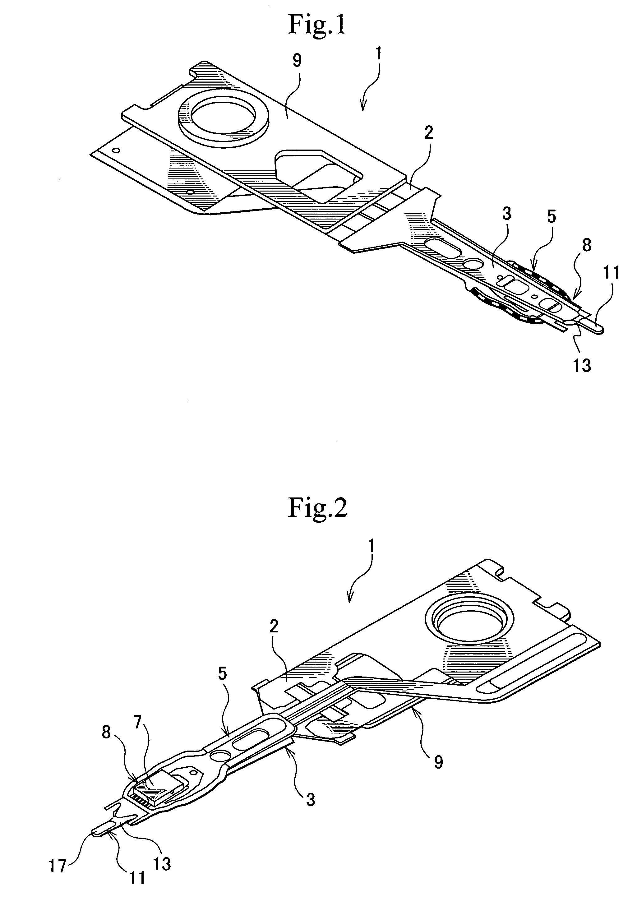
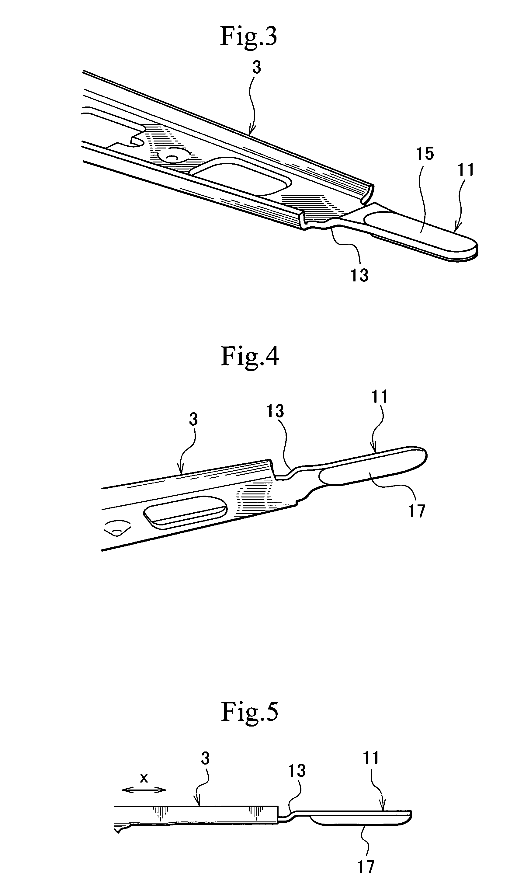
[0052]FIGS. 1 and 2 show a load / unload-type head suspension according to the first embodiment of the present invention, in which FIG. 1 is a perspective view showing a first face of the head suspension and FIG. 2 is a perspective view showing a second face thereof.
[0053]In FIGS. 1 and 2, the head suspension 1 is made of a precision thin plate such as a precision stainless-steel thin plate and includes a load beam 3 and a resilient flexure 5 fixed to the load beam 3. The load beam 3 includes a resilient part 2. The flexure 5 is made of, for example, a thin stainless-steel plate. A slider 7 is fixed to the flexure 5 to form a head 8. The flexure 5 is fixed to the load beam 3 by, for example, laser welding. A base plate 9 is attached to a base of the load beam 3. With the base plate 9, the load beam 3 is fixed to an arm of a carriage.
[0054]The load beam 3 may be made of austenite-based stainless steel such as SUS304 or SUS305. SUS304 is composed of C of 0.08% or be...
second embodiment
[0106]FIGS. 22A and 22B show a load beam of a head suspension according to the second embodiment of the present invention, in which FIG. 22A is a side view partly showing the load beam and FIG. 22B is a perspective view partly showing the load beam.
[0107]The load beam 3A of the second embodiment has a step 13A from which a tab 11A is extended. The tab 11A has a spherical convex face 17A which is provided with microscopic irregularities 19A. A surface roughness Ra of the irregularities 19A is set in the range of 0.2 μm to 0.6 μm.
[0108]With the microscopic irregularities 19A, the second embodiment provides the same effect and operation as those of the first embodiment.
third embodiment
[0109]FIG. 23 is a sectional view partly showing a press used to process a head suspension according to the third embodiment of the present invention. In FIG. 23, the press 21B has an upper mold 23B and a lower mold 25B. The upper mold 23B has a punch 27B. The lower mold 25B has microscopic irregularities 41 to form irregularities 19B of a tab 11B of the head suspension. The irregularities 41 are adjusted to realize a roughness Ra of 0.2 μm to 0.6 μm on the tab 11B.
[0110]The press 21B forms the load beam so that the tab 11B of the load beam may have a convex face 17B which is provided with the microscopic irregularities 19B.
[0111]Accordingly, the third embodiment realizes substantially the same effect and operation as those of the first embodiment. According to the third embodiment, the roughness of the irregularities 41 of the lower mold 25B is adjusted to correctly set a required roughness for the irregularities 19B of the tab 11B.
[0112]The microscopic irregularities of the tab ma...
PUM
| Property | Measurement | Unit |
|---|---|---|
| Ra | aaaaa | aaaaa |
| Ra | aaaaa | aaaaa |
| inclination angle | aaaaa | aaaaa |
Abstract
Description
Claims
Application Information
 - R&D
- Intellectual Property
- Life Sciences
- Materials
- Tech Scout
- Unparalleled Data Quality
- Higher Quality Content
- 60% Fewer Hallucinations
Browse by: Latest US Patents, China's latest patents, Technical Efficacy Thesaurus, Application Domain, Technology Topic, Popular Technical Reports.
© 2025 PatSnap. All rights reserved.Legal|Privacy policy|Modern Slavery Act Transparency Statement|Sitemap|About US| Contact US: help@patsnap.com


