Retaining tool for a heat sink

a technology for retaining tools and heat sinks, which is applied in the direction of electrical apparatus casings/cabinets/drawers, instruments, and semiconductor/solid-state device details, etc., can solve the problems of too little module of elasticity, and achieve good elastic restoration, reduce the possibility of plastic deformation, and easy control

Active Publication Date: 2009-07-07
ASIA VITAL COMPONENTS SHENZHEN CO LTD
View PDF24 Cites 8 Cited by
  • Summary
  • Abstract
  • Description
  • Claims
  • Application Information

AI Technical Summary

Benefits of technology

[0006]In order to overcome the preceding disadvantages, an object of the present invention is to provide a retaining tool for a heat sink with which more module of elasticity is provided in a very limited space and easily controlled engaging force with good elastic restoration can be obtained so as to reduce possibility of plastic deformation.
[0007]Accordingly, a retaining tool for a heat sink includes a frame, at least an operation member and at least an engaging member. The frame is attached to an upper portion of the heat sink with a projection at two opposite sides thereof and the projection has a contact face. The operation member provides a main operation part and a stir part. The main operation part is disposed on top of the contact face and the stir part is angularly lifted for the main operation part being capable of moving relative to the contact face. The engaging member further has a follower part piercing the projection with an end of the follower part connecting with the main operation part pivotally and another end of the follower part being joined to a first elastic part and a second elastic part respectively. The first elastic part extends curvedly a circular bend outward the heat sink and the second elastic part extending curvedly another bend inward the heat sink and free ends of both the elastic parts are joined to two opposite lateral sides of an engaging part for controlling the engaging force evenly and decreasing plastic deformation.

Problems solved by technology

However, the problem of the preceding prior art is in that the elastic part has an insufficient angular bend due to space limitation of a host unit of the computer and it results in too little module of elasticity, which is easy to create plastic deformation while in use.

Method used


Image

  • Retaining tool for a heat sink
  • Retaining tool for a heat sink
  • Retaining tool for a heat sink

Examples


Embodiment Construction

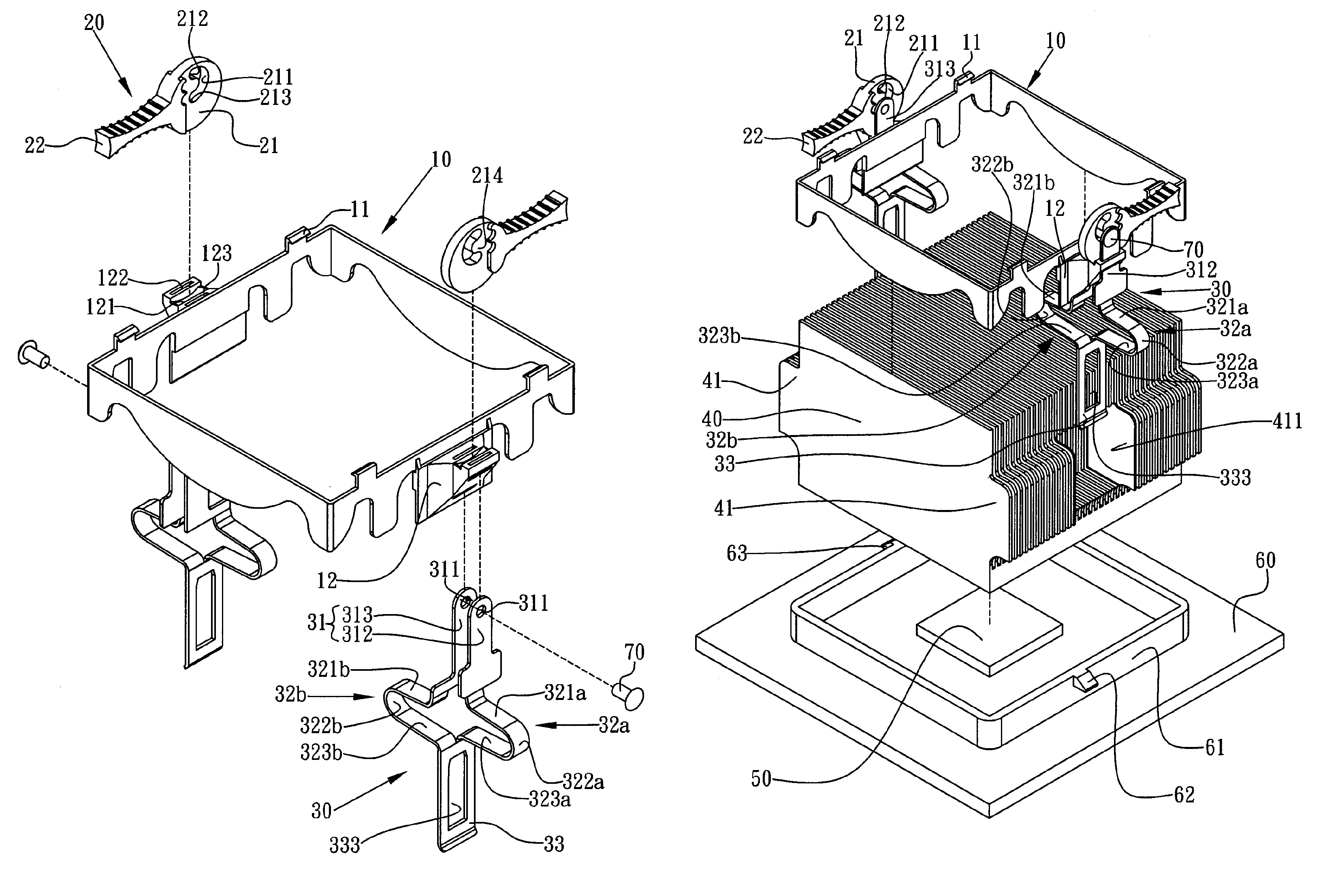
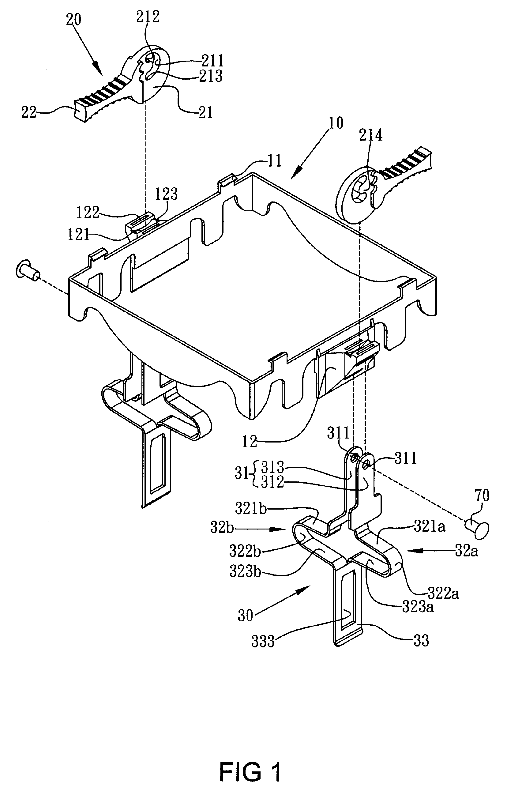
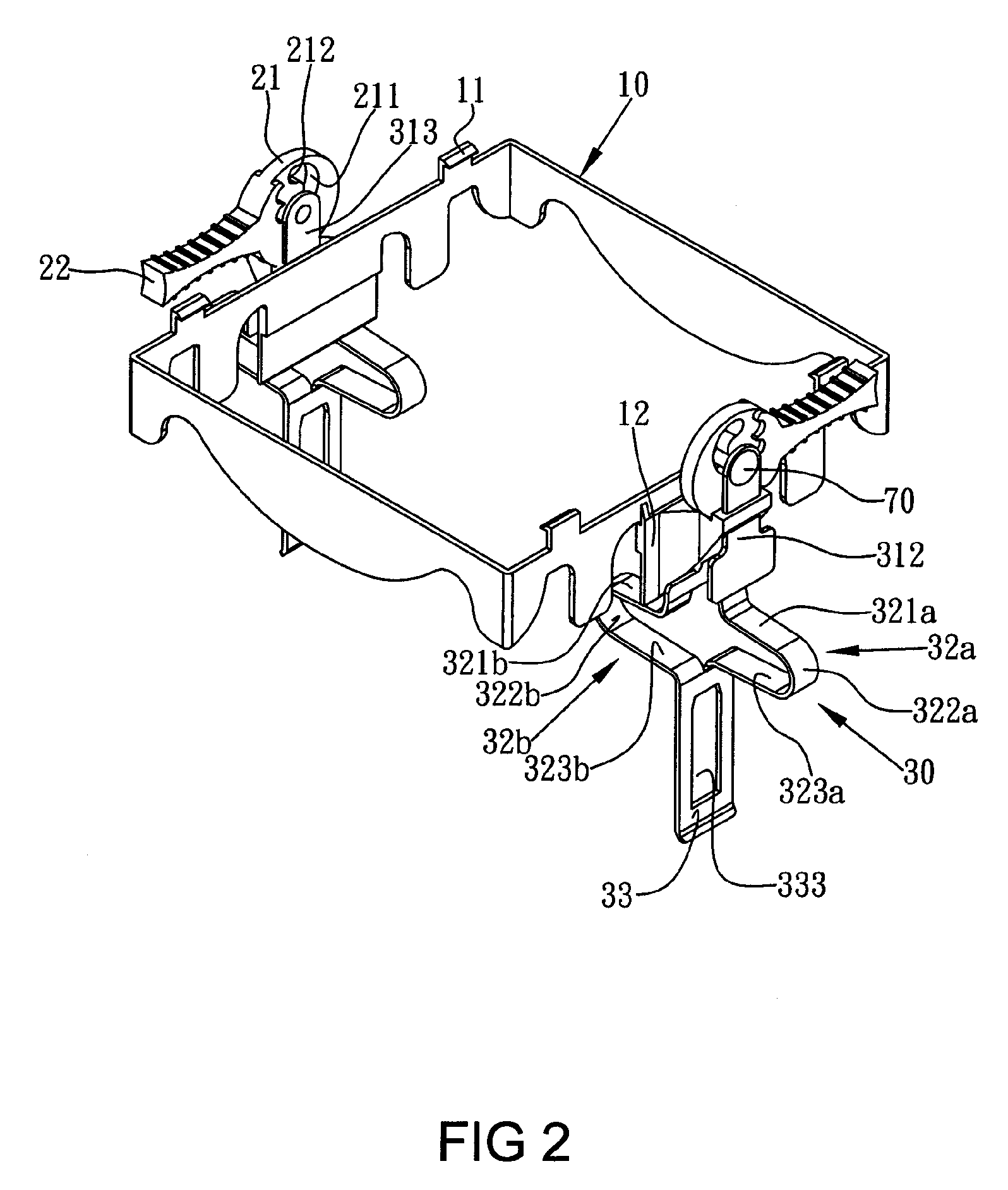
[0016]Referring to FIGS. 1 and 2, the preferred embodiment of a retaining tool for a heat sink according to the present invention includes a frame 10, at least an operation member 20 and at least an engaging member 30. The frame 10 is hollow and provides four enclosed frame edges. Two opposite ones of the frame edges each provide two inverted hooks 11 respectively for engaging a fan (not shown) and extend outward a projection 12 from the middle section thereof. The projection 12 has a contact face 121 with two slots 122, 123.

[0017]The operation member 20 is provided to correspond to the respective projection 12 and includes a main operation part 21 and a stir part 22 extending from the main operation part 21. The main operation part 21 is disposed on top of the contact face 121 of the respective projection 12. The stir part 22 is actuated to rotate the main operation part 21 such that the main operation part 21 is capable of moving relative to the contact face 121.

[0018]The main ope...


PUM


Abstract

A retaining tool for a heat sink includes a frame, at least an operation member and at least an engaging member. The frame is attached to an upper portion of the heat sink with a projection at two opposite sides thereof and the projection has a contact face. The operation member provides a main operation part and a stir part. The main operation part is disposed on top of the contact face and the stir part is angularly lifted for the main operation part being capable of moving relative to the contact face. The engaging member further has a follower part piercing the projection with an end of the follower part connecting with the main operation part pivotally and another end of the follower part being joined to a first elastic part and a second elastic part respectively. The first elastic part extends curvedly a circular bend outward the heat sink and the second elastic part extending curvedly another bend inward the heat sink and free ends of both the elastic parts are joined to two opposite lateral sides of an engaging part for controlling the engaging force evenly and decreasing plastic deformation.

Description

BACKGROUND OF THE INVENTION[0001]1. Field of the Invention[0002]The present invention is related to a retaining tool for a heat sink and particularly to a device for fixing a heat sink.[0003]2. Brief Description of the Related Art[0004]The prior art such as Taiwan Utility Model publication No. 092205232 entitled “Retaining Tool for Heat Dissipation Component” provides a retaining tool being disposed in a locating recess of two opposite sides of a heat dissipation component. The retaining tool has an engaging plate, which is slid into the locating recess with the upper section thereof, providing an elastic part at the middle section thereof and providing an engaging hole at the lower section thereof for engaging a locking ear of a connecting base. The retaining tool further has an operation lever, which provides an actuation plate part being eccentrically joined to the upper section of the engaging plate and the outer contour is disposed on top of the heat dissipation component. Henc...

Claims


Application Information

Patent Timeline
Patent Type & Authority Patents(United States)
IPC IPC(8): H05K7/20A44B21/00F28F7/00A44B99/00
CPCH01L23/4093H01L2924/0002Y10T24/44034H01L2924/00
Inventor LIN, SHENG-HUANG
Owner ASIA VITAL COMPONENTS SHENZHEN CO LTD
Why Eureka
Try Eureka