
Multilevel AC/DC converter for traction applications

a technology of ac/dc converter and traction application, which is applied in the direction of ac-ac conversion, dc-ac conversion without reversal, electric power transfer ac network, etc., can solve the problems of not only saving costs but also weight, and impairing the availability of the power supply system, so as to increase the weight of the above-mentioned power supply system for railway traction applications.

Inactive Publication Date: 2009-07-07
ABB RES LTD
View PDF4 Cites 36 Cited by
  • Summary
  • Abstract
  • Description
  • Claims
  • Application Information

AI Technical Summary

Benefits of technology

"The patent describes a power supply system for railway traction applications that can be increased without adding too much weight. This is achieved by using a multilevel AC / DC converter with frequency conversion and / or a method of converting an AC supply voltage to a DC link voltage. The system includes a traction transformer for isolation, multiple primary converters, and at least two secondary converters. The primary converters are cycloconverters, which are connected in series and output to the traction transformer's primary winding. The secondary converters are connected in parallel to the primary converters and to the traction transformer's secondary winding. The technical effect of this system is that it allows for a more efficient and reliable power conversion for railway traction applications."

Problems solved by technology

Under these circumstances however, a conventional transformer with a nominal frequency of 16.7 Hz or 50 Hz causes integration problems due to its high weight and large volume.
The provision of only one transformer and only one secondary converter is expected to save not only costs but also weight, but obviously impairs the availability of the power supply system.
On the other hand, a voltage source converter (VSC) on the DC side of the transformer operates with hard switching off, resulting in comparatively high stresses on the semiconductor devices of the current valves and high switching losses.
On the other hand, the VSC has no additional or auxiliary semiconductor devices that do not take part in the power conversion itself and merely add to the costs and complexity of the converter.

Method used


Image

  • Multilevel AC/DC converter for traction applications
  • Multilevel AC/DC converter for traction applications

Examples


Embodiment Construction

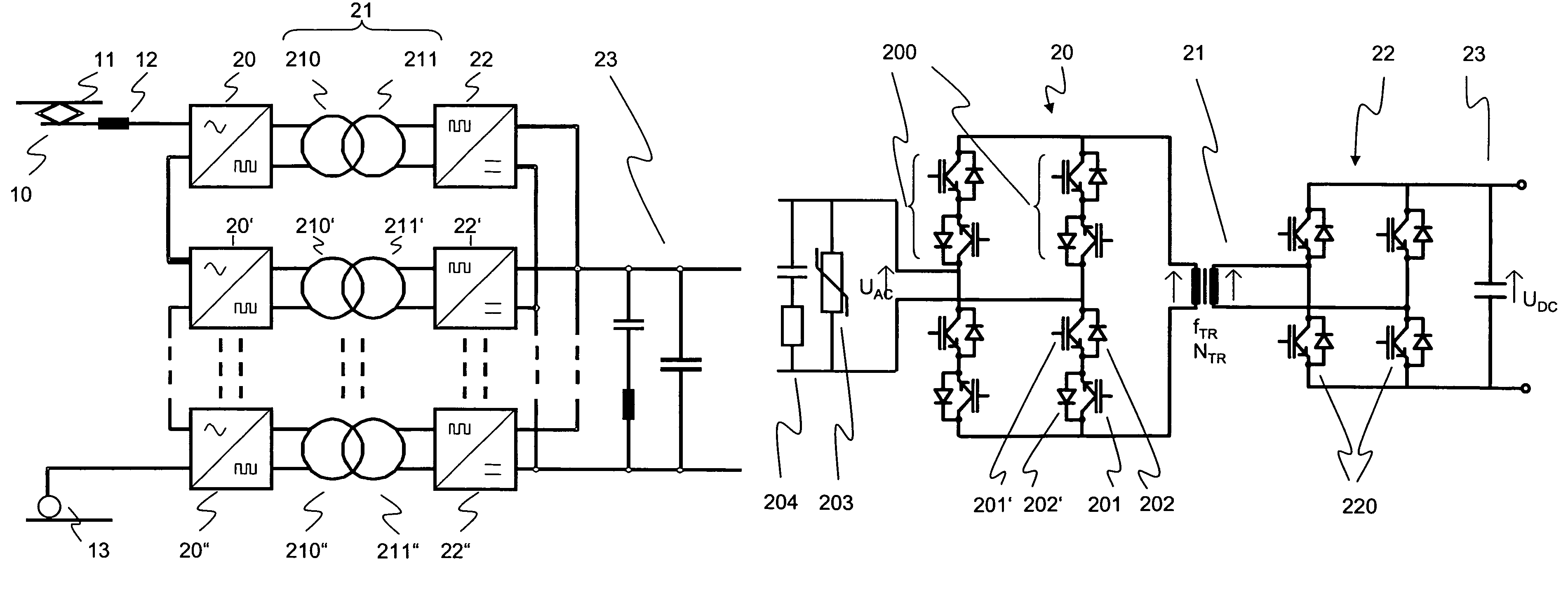
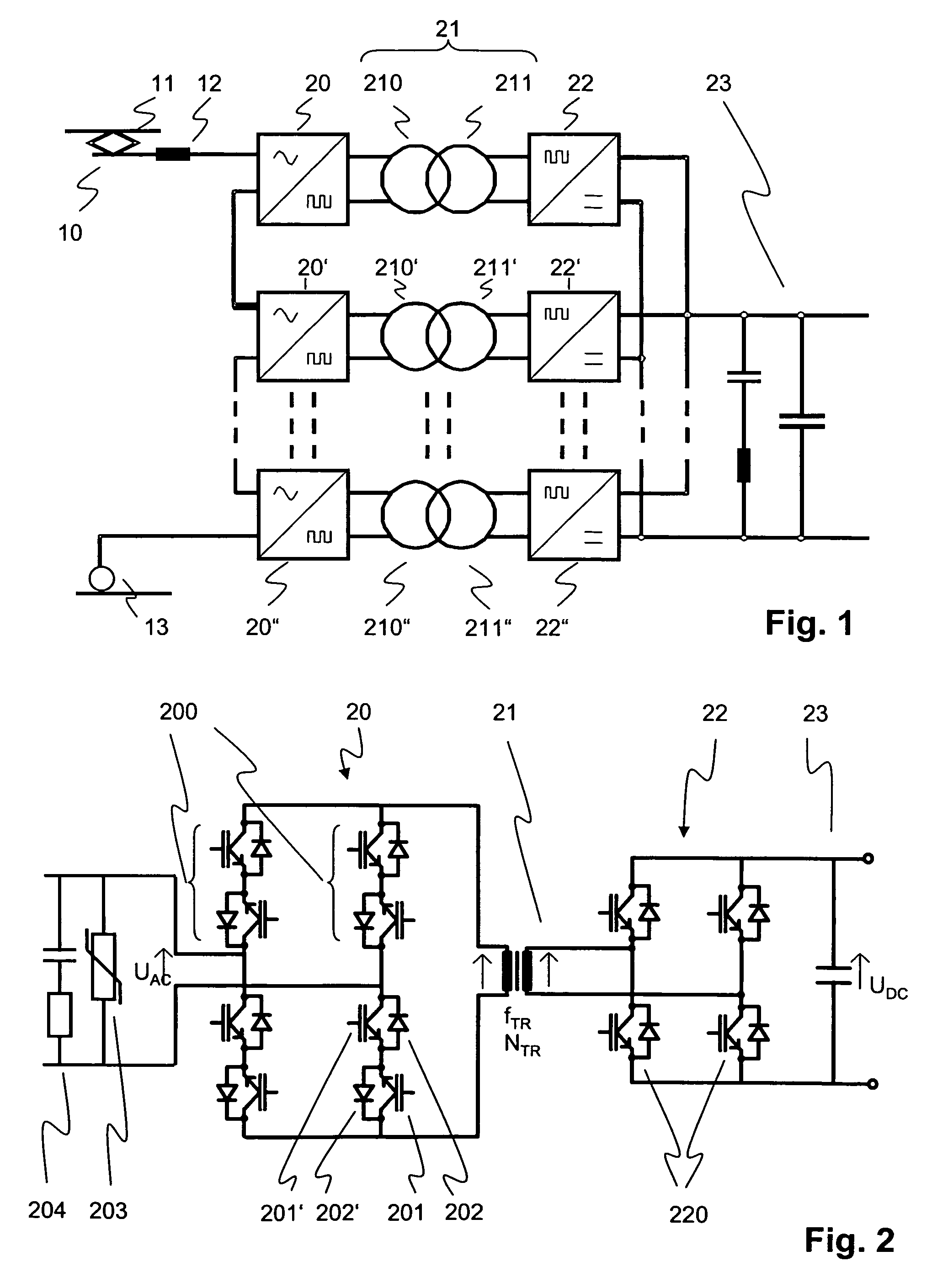
[0017]According to the disclosure, in an exemplary power supply system with a multilevel AC / DC converter comprising a plurality of series-connected primary converters connectable to an AC supply line and a traction transformer operable at a transformer nominal frequency above an AC line frequency, more than one parallel-connected secondary converter connectable to a DC link are provided. In case of failure of one of the secondary converters, the multilevel AC / DC converter may thus continue to operate with reduced power delivered by the remaining secondary converters. In order to compensate for the increase in weight on the secondary side, single-stage cycloconverters or direct AC frequency converters are used as primary converters. The reduced number of power conversion stages and / or components of the cycloconverter as compared to a classical converter topology including an intermediate DC stage furthermore reduce the complexity of the control sequences as well as the overall weight...


PUM


Abstract

A power supply system for railway traction applications including a multilevel AC / DC converter. The converter comprises a plurality of series-connected single-stage cycloconverters or direct AC frequency converters connected between an AC supply line and a traction transformer. The transformer is operable at a transformer nominal frequency below 3 kHz and above the AC line frequency. On the secondary side of the transformer, more than one parallel-connected secondary converter are provided and connected to a DC link. In case of failure of one of the secondary converters, the multilevel AC / DC converter may continue to operate with reduced power delivered by the remaining operating levels.

Description

RELATED APPLICATIONS[0001]This application claims priority under 35 U.S.C. §119 to EP Application 05405462.2 filed in Europe on Aug. 3, 2005, and as a continuation application under 35 U.S.C. §120 to PCT / CH2006 / 000396 filed as an International Application on Jul. 31, 2006 designating the U.S., the entire contents of which are hereby incorporated by reference in their entireties.TECHNICAL FIELD[0002]The disclosure relates to the field of electric railway power supply systems. It departs from a multilevel AC / DC converter for converting a single-phase, line-frequency AC supply voltage of an AC supply line to a DC link voltage of a DC link in railway traction applications.BACKGROUND INFORMATION[0003]Electric railway vehicles such as locomotives or rail coaches powered by an alternating-current (AC) supply line use a traction transformer and an AC / DC converter for converting the high voltage (15 kV or 25 kV) of the supply line to a direct-current (DC) link voltage of a few kV and to ensu...

Claims


Application Information

Patent Timeline
Patent Type & Authority Patents(United States)
IPC IPC(8): H02J3/36H02M7/08
CPCH02M7/219H02M2001/0074H02M5/297H02M7/4807H02M7/49H02M1/0074
Inventor MEYSENC, LUCSTEFANUTTI, PHILIPPENOISETTE, PHILIPPEHUGO, NICOLASAKDAG, ALPER
Owner ABB RES LTD
Learn More