Eureka AIR delivers breakthrough ideas for toughest innovation challenges, trusted by R&D personnel around the world.

Working machine

a technology of working machine and servomotor, which is applied in the direction of servomotor components, servomotors, constructions, etc., can solve the problems of affecting the normal hydraulic pressure transmission of the signal converting device, and achieve the effect of avoiding the cost of configuration

Active Publication Date: 2009-07-14
KOBELCO CONSTR MASCH CO LTD
View PDF20 Cites 5 Cited by
  • Summary
  • Abstract
  • Description
  • Claims
  • Application Information

AI Technical Summary

Benefits of technology

[0010]It is an object of the present invention to provide a working machine having a control apparatus that has an inexpensive configuration including an operating device outputting hydraulic signals, for example, a hydraulic remote control valve and that can control both hydraulic actuators and electric actuators.
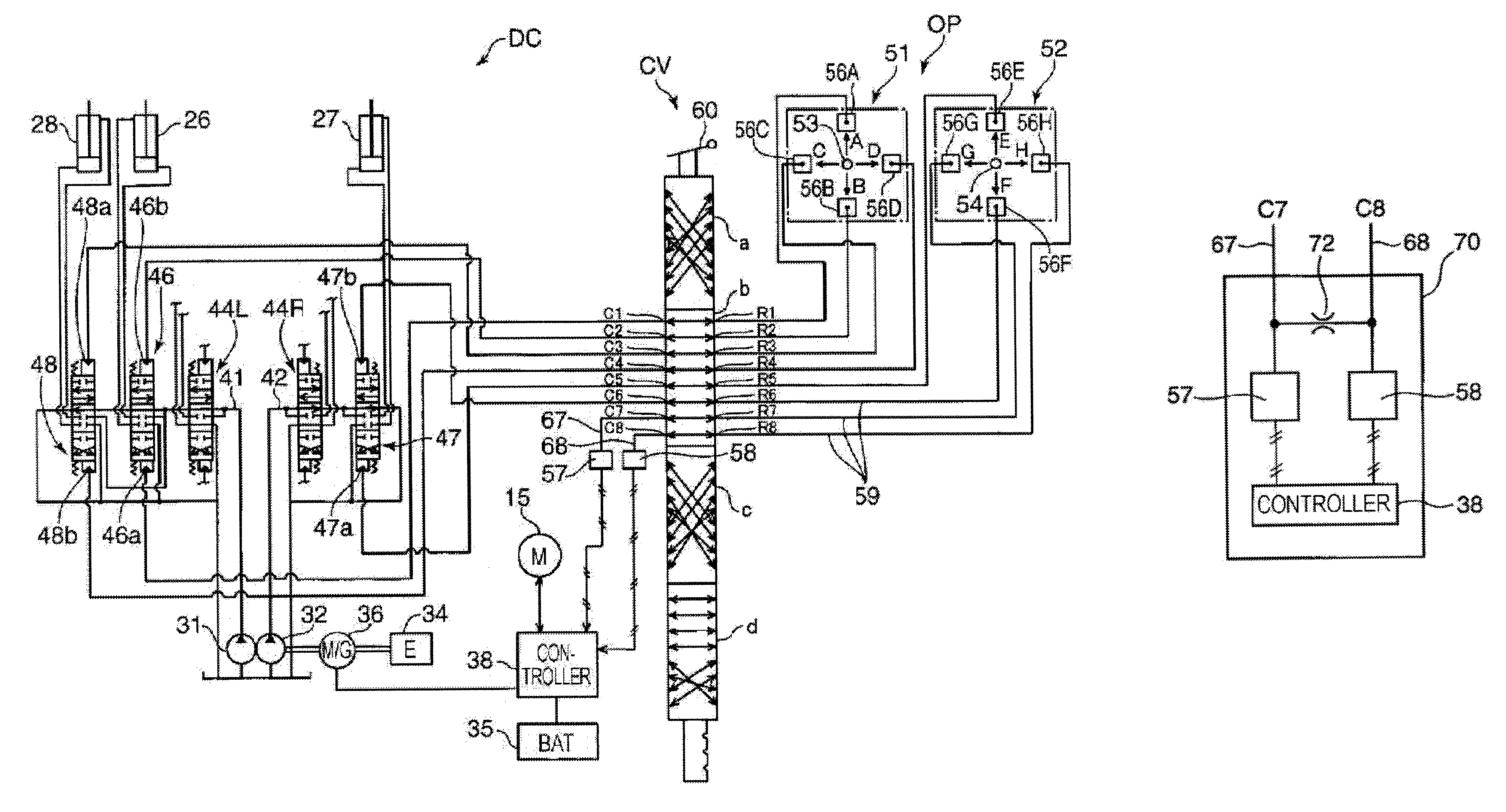
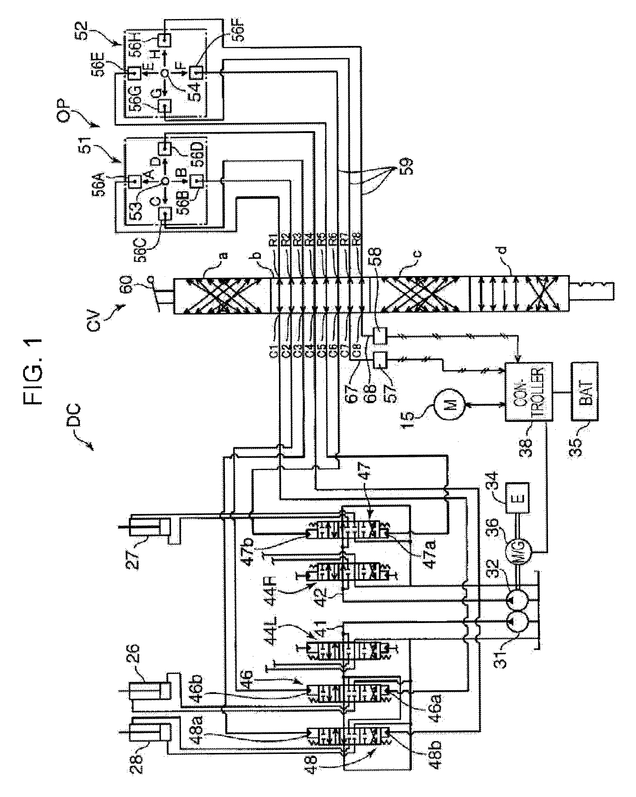
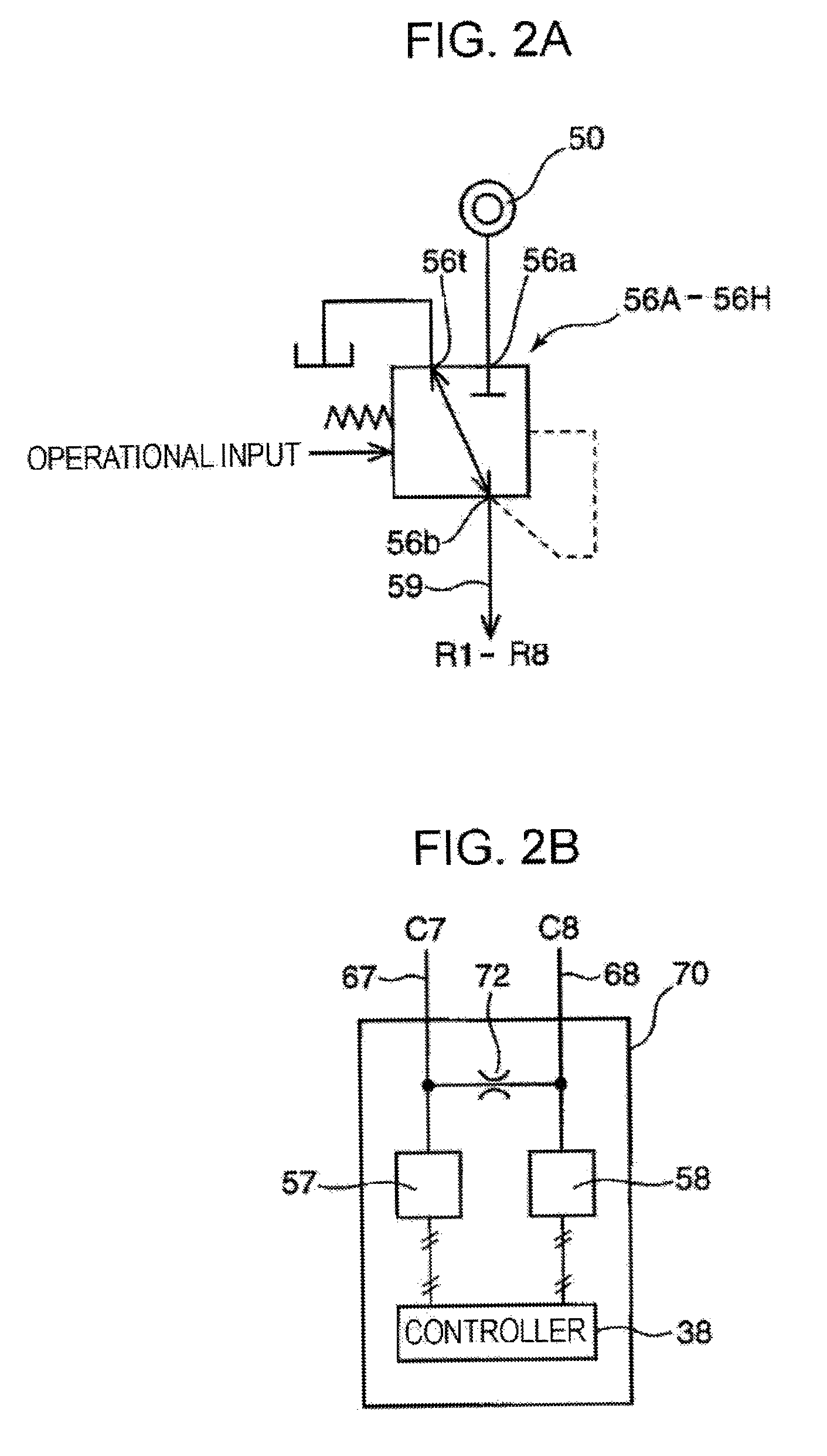
[0016]The first signal output valve and the second signal output valve are alternatively selected by operation of the operating member. When one of the first signal output valve and the second signal output valve is selected by operation of the operating member, the signal output valve supplies hydraulic oil at a hydraulic pressure corresponding to the operation amount of the operating member, to the signal converting device connected to the signal output valve, through the hydraulic oil flow path. On the other hand, the other signal output valve, that is to say, the signal output valve that is not selected by operation of the operating member communicates the hydraulic oil flow path connecting the signal output valve and the signal converting device corresponding to the signal output valve to a tank, thereby performing cancellation of the hydraulic signal. In addition, since the hydraulic oil flow paths are connected to each other via the throttle, air and the like in the hydraulic oil supplied to one of the signal output valves is allowed to escape to the tank side through the throttle, the hydraulic oil flow path connected to the other signal output valve, and the other signal output valve. Therefore, by effectively utilizing the tank-communicating operation performed by one of the signal output valves for canceling the hydraulic signal, air and the like can be effectively prevented from staying before the first signal converting device or the second signal converting device and hindering the signal conversion. Consequently, an excellent signal converting function can be ensured by effectively utilizing the tank-communicating function of the signal output valve that is not selected.
[0021]The first signal converting device and the second signal converting device are preferably housed in a common electromagnetic shield container. In this case, in spite of its simple structure, the control apparatus can effectively prevent the signal conversion function of the signal converting devices from being hindered by external noise.
[0023]In this case, the electric lines can be effectively prevented from being affected by noise. Therefore, the accuracy of electric control can be further improved.

Problems solved by technology

However, if hydraulic oil is simply supplied to the signal converting device through piping in order to input hydraulic signals into the signal converting device, air and the like in the hydraulic oil stay before the signal converting device and can hinder normal hydraulic pressure transmission to the signal converting device.

Method used


Image

  • Working machine
  • Working machine
  • Working machine

Examples


Embodiment Construction

[0029]The preferred embodiment of the present invention will now be described with reference to the drawings. In this embodiment, the present invention is applied to a hydraulic shovel 10 shown in FIG. 3. However, the present invention can also be applied to other working machines, for example, hydraulic cranes, and demolition machines.

[0030]The hydraulic shovel 10 includes a lower traveling body 12 and an upper rotating body 14 rotatably mounted thereon.

[0031]The lower traveling body 12 includes left and right traveling crawlers 16L and 16R. The traveling crawlers 16L and 16R respectively include traveling motors 18L and 18R, which are hydraulic motors for rotating sprockets of the traveling crawlers 16L and 16R.

[0032]The upper rotating body 14 has a rotating electric motor 15 mounted thereon for rotating the upper rotating body 14. In addition, the upper rotating body 14 is provided with a raisable and lowerable boom 20, which serves as a working attachment of the hydraulic shovel...


PUM


Abstract

Of a plurality of hydraulic signals output from an operating device, a hydraulic signal is input into a control valve serving as a hydraulic control device without conversion, and particular hydraulic signals are converted into electric signals corresponding to their hydraulic pressures by signal converting devices, such as pressure sensors, and are then input into a controller. The controller controls the drive of an electric actuator, such as a rotating electric motor, on the basis of the electric signals. Hydraulic fluid flow paths communicating to the pressure sensors are connected to each other via a throttle, and air in one of the hydraulic fluid flow paths is removed using the other hydraulic fluid flow path.

Description

BACKGROUND OF THE INVENTION[0001]1. Field of the Invention[0002]The present invention relates to a working machine having an apparatus that controls the operation of a plurality of actuators according to the operation of an operating member by an operator.[0003]2. Description of the Related Art[0004]The following techniques are known as apparatuses that control the operation of a plurality of actuators according to the operation of an operating lever by an operator.[0005]Japanese Examined Utility Model Registration Application Publication No. 7-48761 discloses an apparatus including a plurality of hydraulic remote control valves that output a hydraulic pressure according to the operation amount of an operating lever, and pilot switching valves connected to actuators. The hydraulic pressure output from the remote control valves is input as a pilot pressure into a pilot chamber of one of the switching valves. According to circumstances, the user can switch between a plurality of combi...

Claims


Application Information

Patent Timeline
Patent Type & Authority Patents(United States)
IPC IPC(8): F15B13/02
CPCE02F9/2004E02F9/2012E02F9/2292E02F9/2228E02F9/2075
Inventor KOMIYAMA, MASAYUKISORA, TOSHIO
Owner KOBELCO CONSTR MASCH CO LTD
Why Eureka
Eureka Blog
Learn More