Retractable float for a ballcock valve

a technology of float and ballcock valve, which is applied in the direction of valve details, valve arrangement, thin material handling, etc., can solve the problems of bulky wrap-around float and the rather complex operation of predetermined water level adjustment with conventional valve systems

Inactive Publication Date: 2009-07-14
FLUIDMASTER
View PDF18 Cites 7 Cited by
  • Summary
  • Abstract
  • Description
  • Claims
  • Application Information

AI Technical Summary

Problems solved by technology

A wrap-around float is usually bulky in order to provide sufficient buoyancy for driving the valve piston.
Accordingly, conventional ballcock valves are packaged with the rod and the float unassembled, as the rod and the float take too much space and are susceptible to damages if packaged and transported fully assembled.
In addition, it is a rather complex operation to adjust the predetermined water level with conventional valve systems.

Method used


Image

  • Retractable float for a ballcock valve
  • Retractable float for a ballcock valve
  • Retractable float for a ballcock valve

Examples


Embodiment Construction

[0034]The invention and its various embodiments can now be better understood by turning to the following detailed description wherein illustrated embodiments are described. It is to be expressly understood that the illustrated embodiments are set forth as examples and not by way of limitations on the invention as ultimately defined in the claims.

[0035]A ballcock valve system according to the invention has adjustable positions for storage and packaging, and for adjusting water levels.

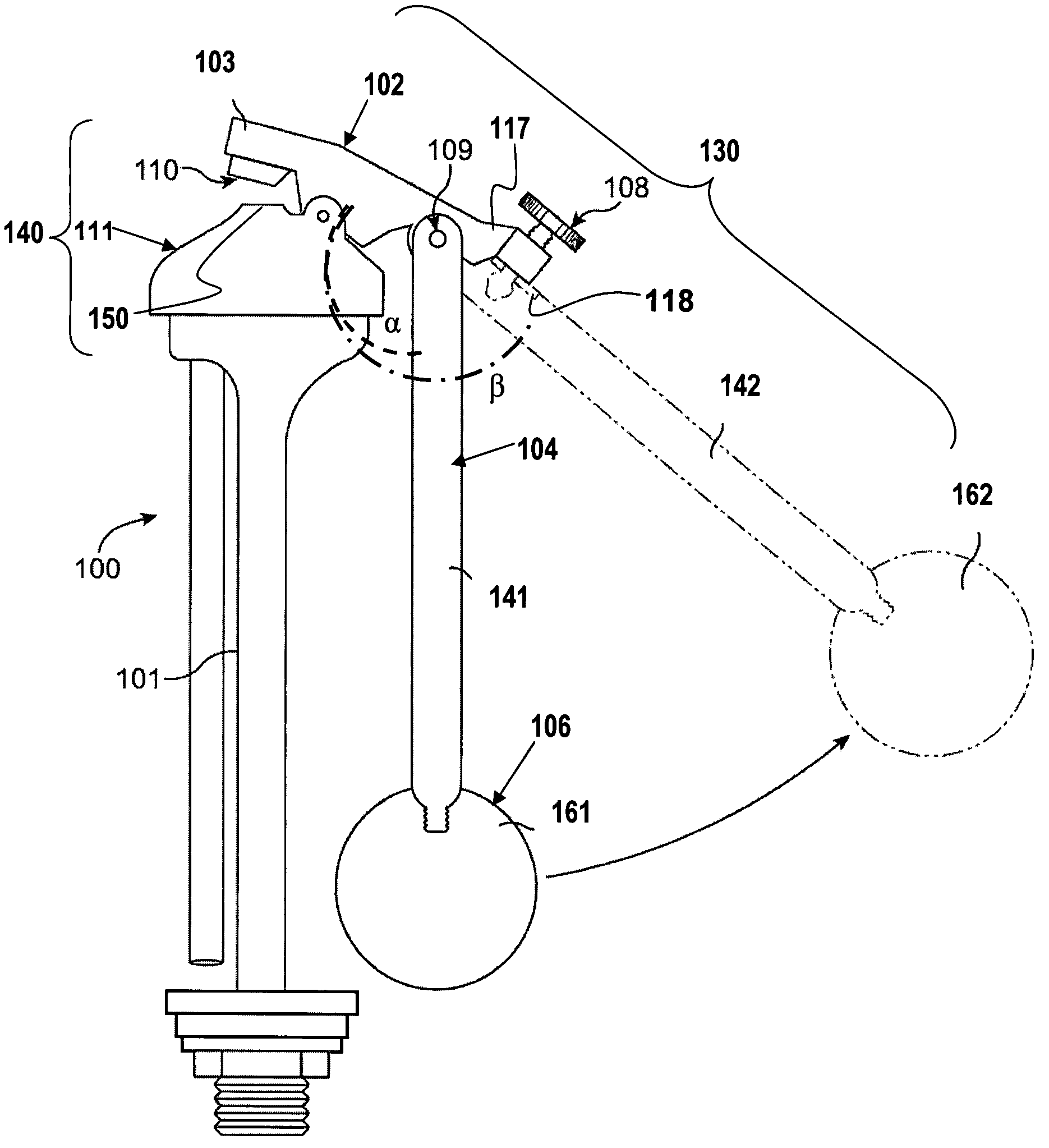
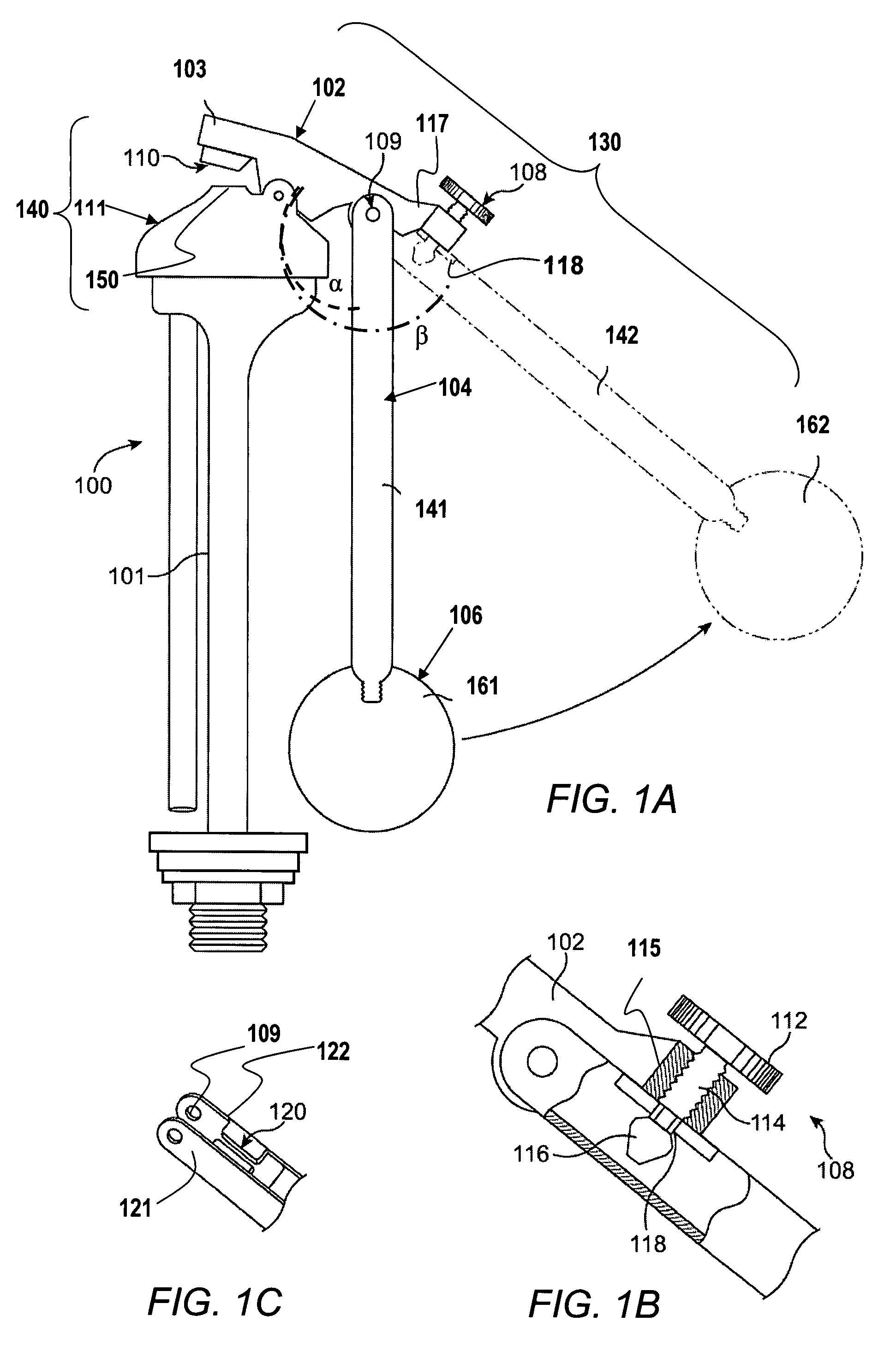
[0036]FIG. 1A is a side view of a first preferred embodiment of the ballcock valve system 100. The system 100 comprises a collapsible lever 130 coupled to a valve 140 and a buoyancy device 106. In the first preferred embodiment, the collapsible lever 130 comprises a first movable member 102, such as a proximal rod, and a second movable member 104, such as a distal rod, movably coupled to the first rod 102 at a hinge post 109. The second rod 104 is coupled to a floating device 106, such as a ball-shaped f...


PUM


Abstract

A collapsible floating apparatus for controlling a valve includes a floating device and a collapsible lever. The collapsible lever includes a first member rotatably coupled to the valve, and a second member attached to the floating device at one end and rotatably coupled to the first member adjacent another end. The apparatus has a retracted position for shipping and storage, and operational positions. In the position, the second member, or the first and second members together, are brought adjacent to the valve. In operational positions, the first and second members act as a single lever to relay the buoyancy of the floating device drives to the valve. An adjusting member is provided for adjusting a relative position or angle between the first and second members, which in turn adjusts a water level.

Description

RELATED APPLICATIONS[0001]This application relates to, claims priority from, and incorporates herein by reference, as if fully set forth, U.S. Provisional Patent Application Ser. No. 60 / 815,055 filed on Jun. 19, 2006 and entitled “RETRACTABLE FLOAT, PILOT BALLCOCK VALVE.”BACKGROUND OF THE INVENTION[0002]1. Field of the Invention[0003]The present invention relates generally to toilet flushing systems and particularly to valves for toilets.[0004]2. Description of Prior Art and Related Information[0005]Conventional toilet tanks employ plug and flapper tank valves that are levered open, which remain open while a full tank is emptied. A piston-operated ballcock valve is open whenever the water level in the tank is below a predetermined level. While the ballcock valve is open, part of its total flow is diverted to refill the bowl at the same time the tank is being refilled by the valve.[0006]The piston is driven by a float. The float may be a wrap-around float, which partially wraps aroun...

Claims


Application Information

Patent Timeline
Patent Type & Authority Patents(United States)
IPC IPC(8): F16K31/18
CPCF16K31/34Y10T137/7413Y10T137/7475Y10T137/7488Y10T137/7423
Inventor HAN, JOSEPH
Owner FLUIDMASTER
Why Eureka
Try Eureka