Sump pump with emergency backup system

Active Publication Date: 2009-08-20
EVERDRY MARKETING & MANAGEMENT
View PDF3 Cites 69 Cited by
  • Summary
  • Abstract
  • Description
  • Claims
  • Application Information

AI Technical Summary

Benefits of technology

[0009]In accordance with another aspect of the present disclosure, a flood control system comprises a sump for gathering subterranean water for removal from the structure. An AC operated main pump and a DC operated secondary pump are positioned in the sump. An elevating member is located in the sump for raising a height of the secondary pump relative to the main pump. A cover is releasably mounted to the sump. The cover includes a first section for covering the main pump an

Problems solved by technology

Unfortunately, the sump pump may not function when needed in an emergency because of a power failure or it may fail to operate because, for example, the level sensing device fails to operate.
There are other factors that may result in the sump pump becoming inoperative, such as corrosion of certain pump parts, or clogging of the sump pump as a result of debris accumulating in the sump.
Unfortunately, these auxiliary DC systems have left much t

Method used


Image

  • Sump pump with emergency backup system
  • Sump pump with emergency backup system
  • Sump pump with emergency backup system

Examples


Embodiment Construction

[0020]It should, of course, be understood that the description and drawings herein are merely illustrative and that various modifications and changes can be made in the structures disclosed without departing from the present disclosure. It will also be appreciated that the various identified components of the sump pump with an emergency backup system disclosed herein are merely terms of art that may vary from one manufacturer to another and should not be deemed to limit the present disclosure. All references to direction and position, unless otherwise indicated, refer to the orientation of the sump pump with an emergency backup system illustrated in the drawings and should not be construed as limiting the claims appended hereto.

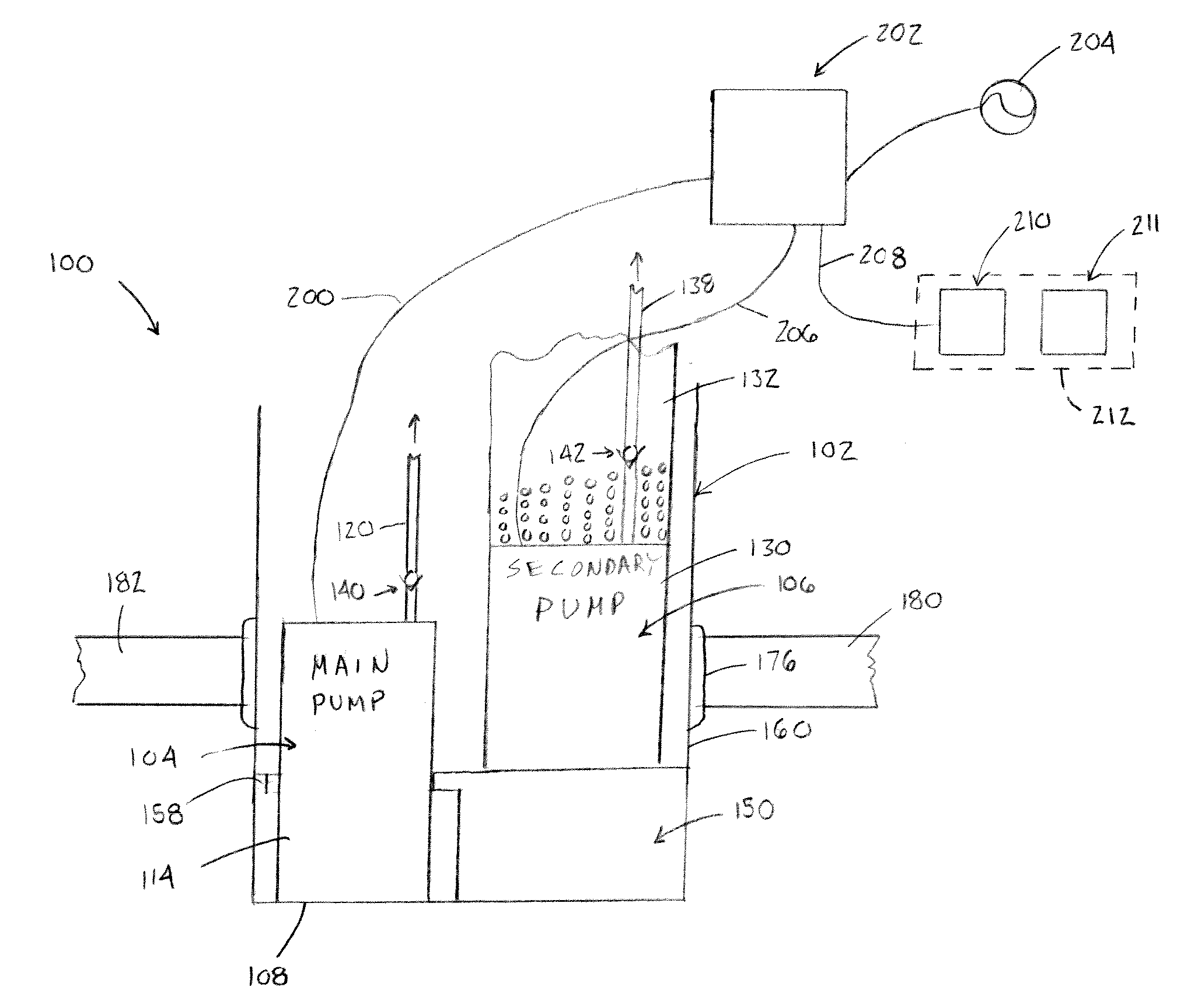
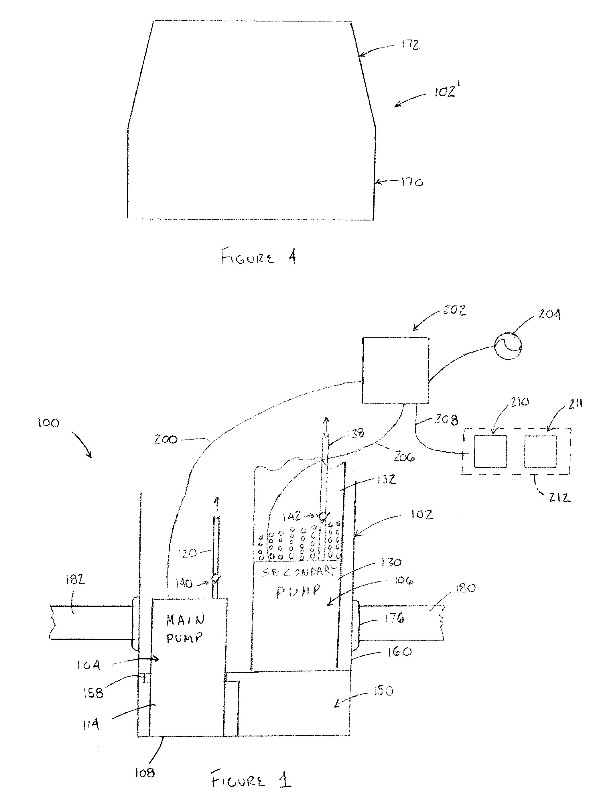
[0021]Referring now to the drawings, wherein like numerals refer to like parts throughout the several views, FIG. 1 illustrates a sump pump with an emergency backup system 100 according to the present disclosure. The system 100 comprises a sump or crock 102 w...


PUM


Abstract

A flood control system for use in a structure having a basement floor below ground level is provided. The flood control system comprises a sump, a main pump positioned in the sump, and a secondary pump positioned in the sum. The secondary pump is raised relative to the main pump to a predetermined elevation. The main pump is energized when a height of water within the sump is at a first level. The secondary pump is energized when a height of water within the sump reaches a second, higher level and is de-energized when a height of water within the sump drops to a third level. A cover is releasably mounted to the sump. The cover includes a first section for covering the main pump and a separate second section for covering the secondary pump. At least one of the first and second sections is hingedly mounted to the sump. A controller is operatively connected to the main pump and the secondary pump. The controller is responsive to water level within the sump to selectively energize at least one of the main pump and the secondary pump.

Description

RELATED APPLICATIONS[0001]This application claims priority from U.S. Provisional Patent Application Ser. No. 61 / 030,102, filed 20 Feb. 2008, the disclosure of which is incorporated herein by reference.BACKGROUND[0002]The present disclosure relates to the control of subterranean water. Particularly, the present disclosure relates to a sump pump with an emergency backup system for use in a structure having a basement floor located below ground level, which must be kept free of the ingress of subterranean water.[0003]In structures, such as homes, having basements or cellars which extend below ground level, it is imperative that the ingress of water be prevented so that the basement space may remain usable. To that end, structures typically have footing drains leading to a sump or other similar collection basin, from which water is removed via a sump pump. It is a common practice in many areas of the United States to provide the sump in the floor of the basement.[0004]A typical sump pum...

Claims


Application Information

Patent Timeline
IPC IPC(8): F04B41/06
CPCF04D15/0077F04D15/029F04D15/0209
Inventor MOORE, CARL P.BRADLEY, CHAD J.
Owner EVERDRY MARKETING & MANAGEMENT
Why Eureka
Try Eureka