Clamp device for temporarily closing flexible pipes without pipe wall damage

a flexible pipe and hose technology, applied in the direction of diaphragm valves, engine diaphragms, valve arrangements, etc., can solve the problems of not being completely satisfactory, not being convenient or feasible to close a permanently installed valve, increasing the likelihood of leakage and other failures immediately or subsequently, etc., to achieve uniform compression and facilitate the application of controlled force

Inactive Publication Date: 2009-07-14
GRIMES DENNIS L
View PDF19 Cites 16 Cited by
  • Summary
  • Abstract
  • Description
  • Claims
  • Application Information

AI Technical Summary

Benefits of technology

[0005]The present invention provides a clamping device that overcomes the disadvantages and drawbacks of the prior art. The device of the invention includes two clamping members or jaws that are hinged at an offset, so that when the device is fully closed the jaws are parallel but spaced apart an appropriate distance to accommodate the thickness of the pipe wall without excessive compression, and with uniform compression across the width of the compressed portion of the pipe. The device of the invention also includes a unique closing and fastening mechanism that greatly facilitates application of controlled force, in confined spaces, to close the pipe without damaging the pipe wall. The structure and features of the device of the invention will be described in detail below, with reference to the accompanying drawing figures.

Problems solved by technology

When an operation such as a repair or a modification, such as the addition of a branch line, is to be performed on a flexible hose or pipe it may not be convenient or feasible to close a permanently installed valve to shut down the flow through the pipe where the repair or other work operation is to be performed.
It is important in performing the clamping operation to avoid damage to the pipe, because such damage creates a weak spot in the pipe and increases the likelihood that leaks and other failures will immediately or subsequently develop
Devices for temporarily clamping pipes are known in the prior art, but the prior art devices have certain inherent disadvantages and none of them has proved to be completely satisfactory.
As a result, the space between them adjacent to the hinge is less than the space between them near their outer ends, and the pipe is not uniformly compressed.
When sufficient force is applied to fully close the pipe to fluid flow the portion of the pipe wall nearest the hinge of the device is often excessively compressed and damaged.
However, the additional length can make such devices difficult to use in a confined space, such as a trench, without additional excavation.

Method used


Image

  • Clamp device for temporarily closing flexible pipes without pipe wall damage
  • Clamp device for temporarily closing flexible pipes without pipe wall damage
  • Clamp device for temporarily closing flexible pipes without pipe wall damage

Examples


Embodiment Construction

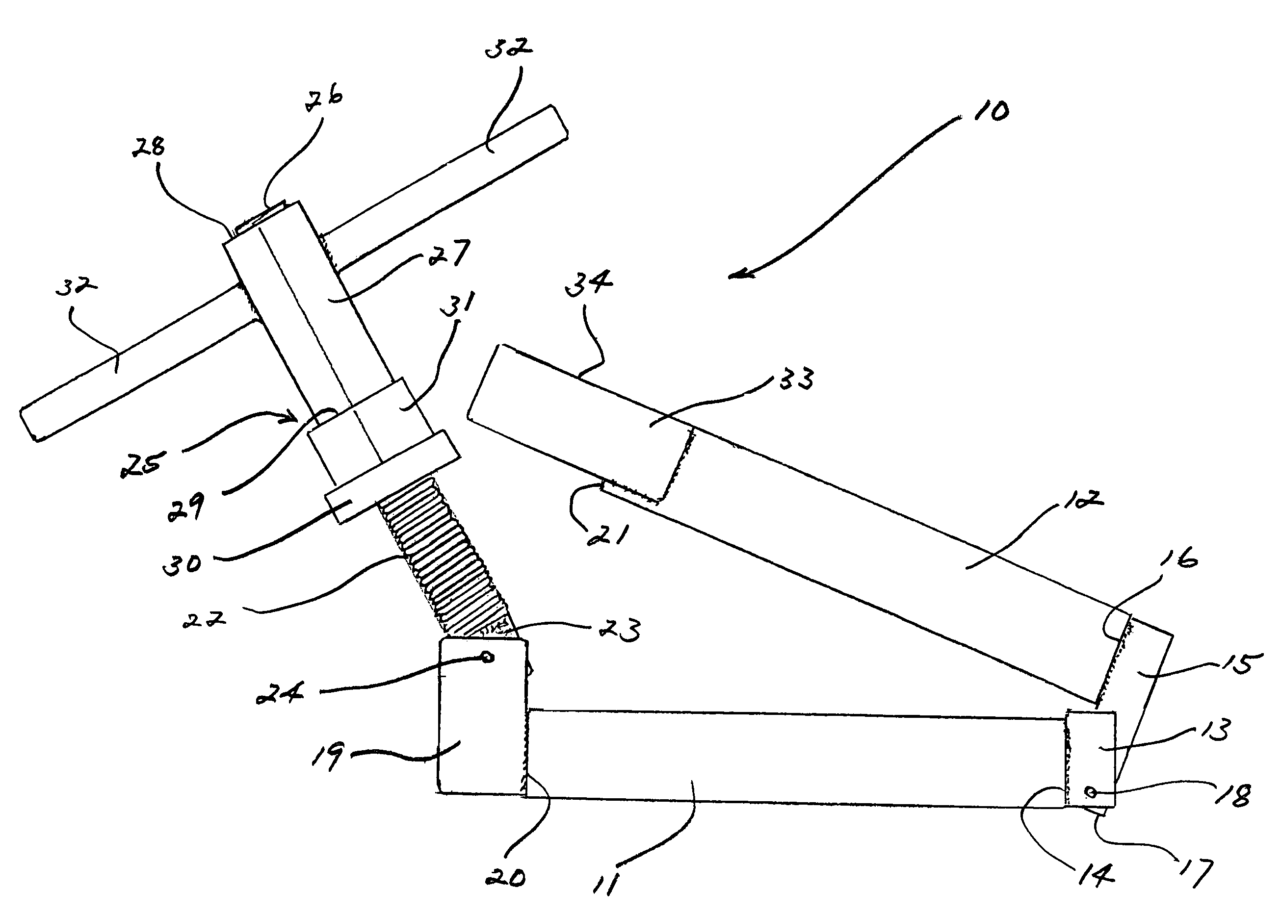
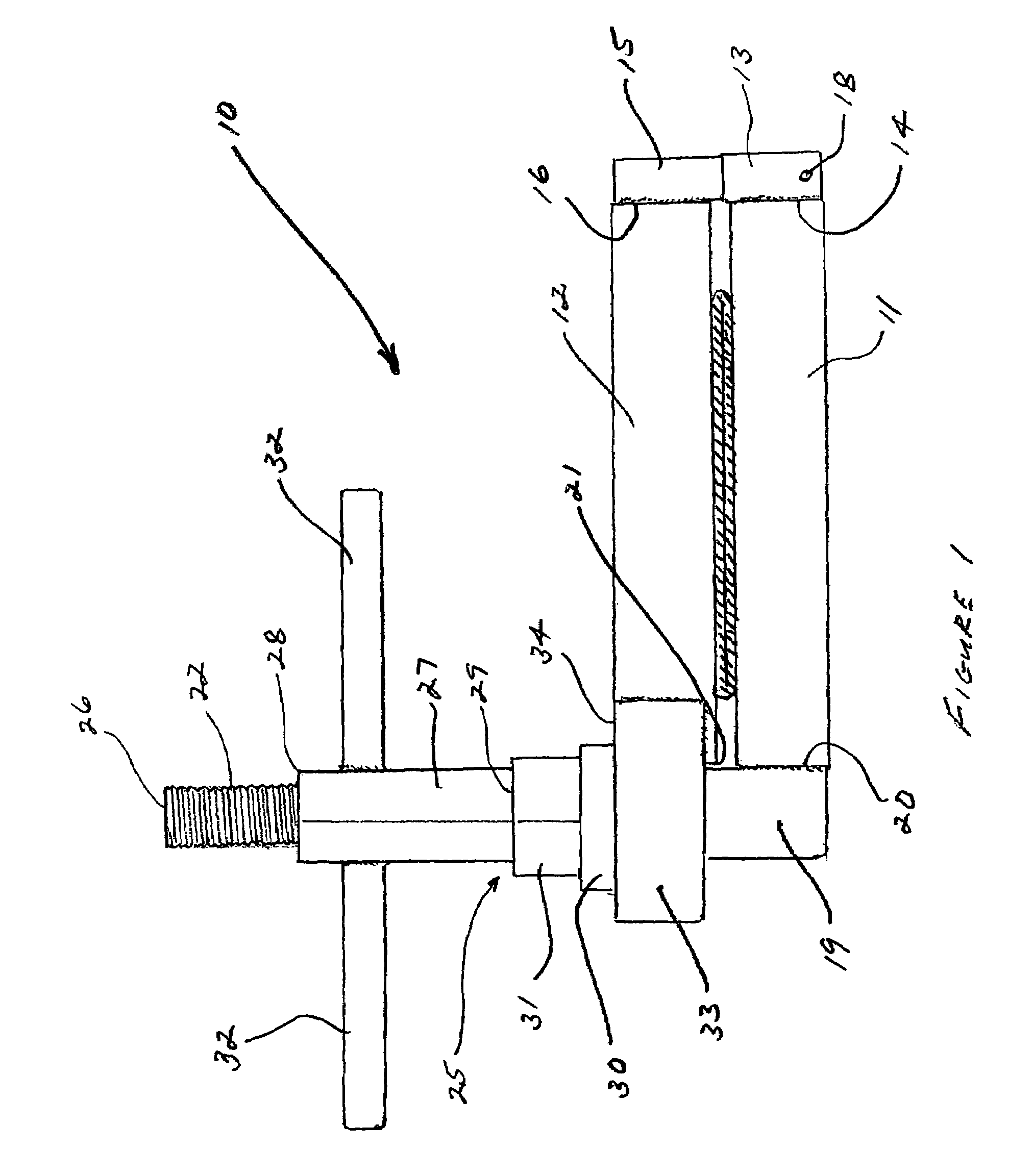
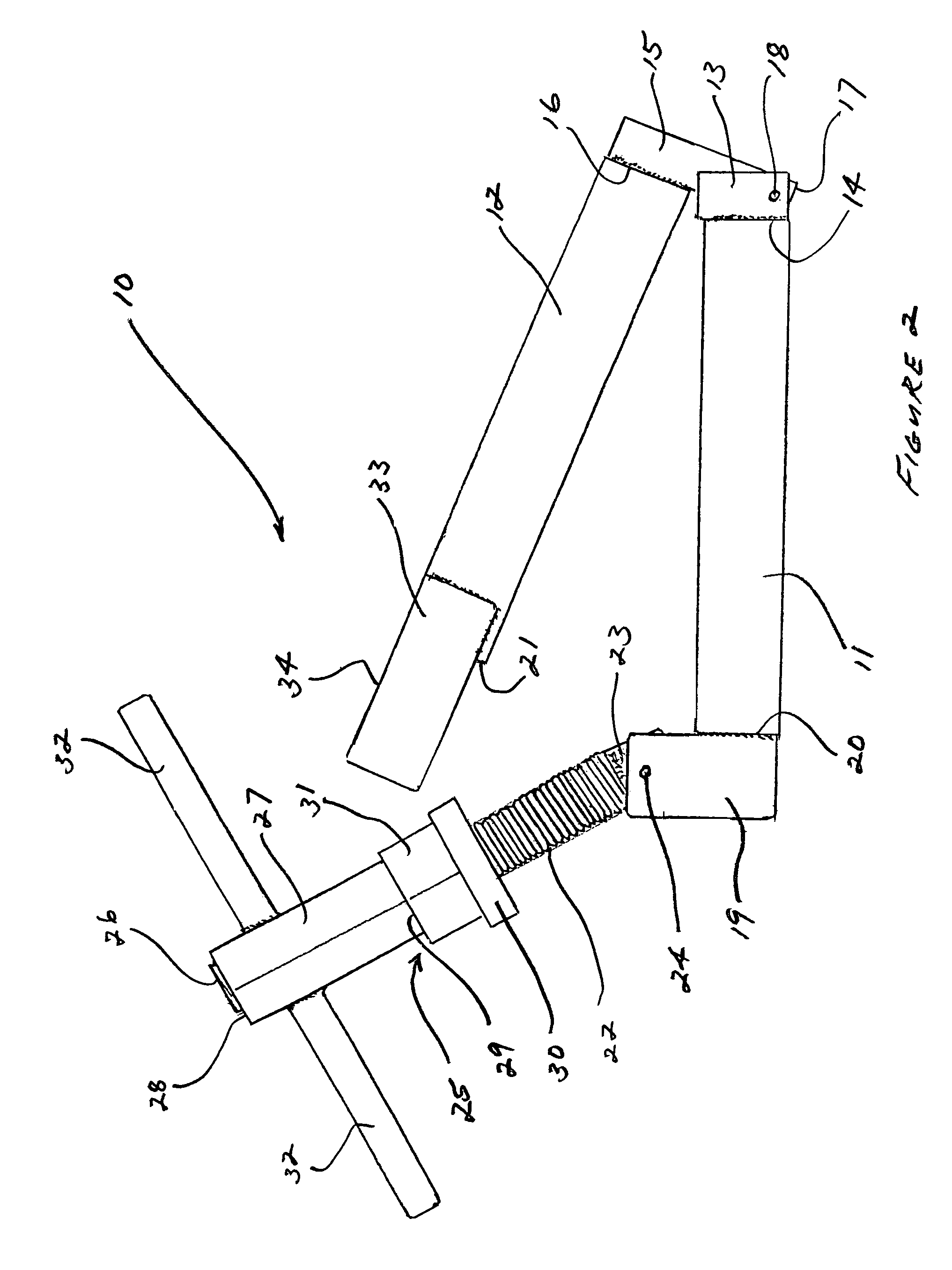
[0014]The preferred embodiment of the clamping device of the invention, generally identified by reference number 10, includes a first, or lower, jaw member 11, and a second, or upper jaw member 12, to be positioned below and above, respectively, a flexible pipe to be compressed and temporarily closed. In the preferred embodiment both jaws 11 and 12 are formed of round steel rods. The round configuration avoids the presence of corners or projections that might damage pipe walls, and the steel material provides sufficient strength and rigidity to avoid deformation of the device and assure maintenance of a secure closure. However, the specific configuration and material of construction are both subject to variation within the scope of the invention, and other configurations and materials could be used if desired. As a non-limiting example, jaws 11 and 12 could be formed of sections of heavy walled pipe rather than solid rods, to reduce the weight of the device, so long as the pipe is o...


PUM


Abstract

A device for temporarily closing a flexible pipe against the flow of fluid through the pipe includes upper and lower jaw members pivotally connected at their first ends to receive and compress the pipe between the jaw members, with pipe engaging surfaces of the jaw members separated from each other to prevent excessive compression of the pipe. An elongate threaded rod is pivotally connected to the second end of the lower jaw member, to extend between bearing plates connected to and extending outwardly from the second end of the upper jaw member. A nut assembly is threaded onto the threaded rod to be received and tightened against the bearing plates to safely compress the pipe between the jaw members without damaging the pipe wall.

Description

RELATED APPLICATION DATA[0001]This application claims the benefit of U.S. Provisional Patent Application Ser. No. 60 / 733,875, filed Nov. 7, 2005, and titled “Clamp Device For Temporarily Closing Flexible Pipes”.FIELD OF THE INVENTION[0002]The present invention generally relates to clamp devices for hoses and pipes, and in its preferred embodiments more specifically relates to a device for temporarily shutting off the flow of pressurized fluids through a flexible hose or pipe for repair or other work operations.BACKGROUND[0003]It is increasingly common for flexible pipes and hoses to be used to convey fluids. When an operation such as a repair or a modification, such as the addition of a branch line, is to be performed on a flexible hose or pipe it may not be convenient or feasible to close a permanently installed valve to shut down the flow through the pipe where the repair or other work operation is to be performed. In those instances it is common practice to use a temporary clampi...

Claims


Application Information

Patent Timeline
Patent Type & Authority Patents(United States)
IPC IPC(8): F16K7/04
CPCF16K7/063F16K7/061
Inventor GRIMES, DENNIS L.
Owner GRIMES DENNIS L
Why Eureka
Try Eureka