Fuel cell stack compression assembly

a fuel cell stack and compression assembly technology, applied in the field of fuel cell stacks, can solve the problems of non-uniform compression non-repair of the fuel cell stack, and non-repair of the fuel cell stack, and achieve the effect of uniform compression and effective mounting methods

Inactive Publication Date: 2006-08-24
CONNECTICUT INNOVATIONS
View PDF0 Cites 13 Cited by
  • Summary
  • Abstract
  • Description
  • Claims
  • Application Information

AI Technical Summary

Benefits of technology

[0017] In accordance with another aspect, a support structure that permits the installation of the fuel cell into a framework is attached to one of or both of the compression distribution plates, preferably at the central unitary section in a manner that allows the ability of the extension elements of the compression distribution plates to deflect in the manner intended. In a preferred embodiment, the fastening method utilizes a three-point attachment and utilizes fasteners of the type known by those skilled in the art to provide the requisite safety and strength. Ideally, the fastening method should be independent of the orientation of the fuel cell so as to provide the system designer with the maximum flexibility to position the fuel cell stack within the network of piping and enclosures so as to achieve efficiency of system packaging. From a structural viewpoint, the compression distribution plates provide desirable mounting points due to its strength and rigidity relative to other components of the fuel cell stack. The points of attachment and the fuel cell's orientation must be selected so as to minimally impact the compression assembly's ability to uniformly apply a compressive load to the fuel cell stack.
[0020] It will be recognized by the person of ordinary skill in the art, given the benefit of this disclosure, that the compression assembly apparatus and methods of use provides numerous advantages including, but not limited to, maintaining a substantially uniform compression to an operating fuel cell or fuel cell stack and to provide more effective mounting methods for fuel cells and fuel cell stacks.

Problems solved by technology

The process of heat generation and heat removal typically does not occur uniformly throughout the fuel cell.
These thermal gradients produce differential thermal expansions and contractions along these axes that can create non-uniform compression of the fuel cell stack due to inflexibility of the stack compression assembly.
This results in an ever-changing environment of differential thermal expansions and contractions that can materially affect the performance of the fuel cell.
Furthermore, the physical tolerances that exist within the dimensions of the individual cells of the fuel cell stack at the point of manufacture may accumulate in a manner that produces non-parallelism of the major surfaces of the end cells of the fuel cell stack, which can be disadvantageous when applying and maintaining a uniform compressive load to the fuel cell stack.
Also, the constant application of compression to the fuel cell stack over the lifetime operation of the fuel cell stack at its elevated operating temperature results in mechanical creep that alters the physical dimensions of the fuel cell stack.
The result is that the stack becomes shorter over time.
The creep may not occur uniformly due to temperature gradients in the fuel cell or due to non-symmetrical physical construction of the fuel cell or due to other electrochemical effects.
In general, compression assemblies of the prior art have not been entirely effective in absorbing dimensional non-uniformities caused by stack differential thermal expansions and contractions, accumulated tolerances of the fuel cell stack, and mechanical creep.
Also, compression assemblies of the prior art have generally not effectively provided the ability to universally mount the fuel cell in a manner that minimally impacts the compression assembly's ability to uniformly apply a compressive load to the fuel cell stack.

Method used


Image

  • Fuel cell stack compression assembly
  • Fuel cell stack compression assembly
  • Fuel cell stack compression assembly

Examples


Embodiment Construction

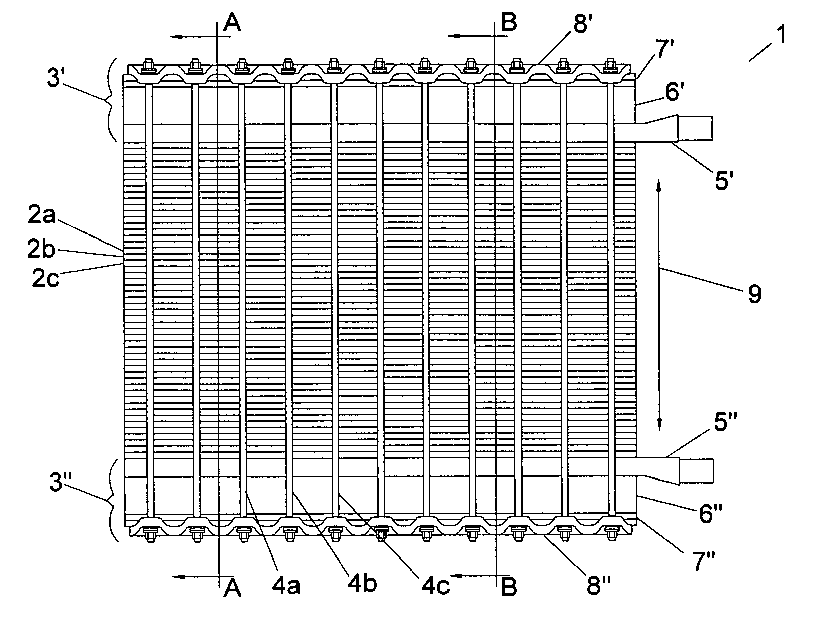
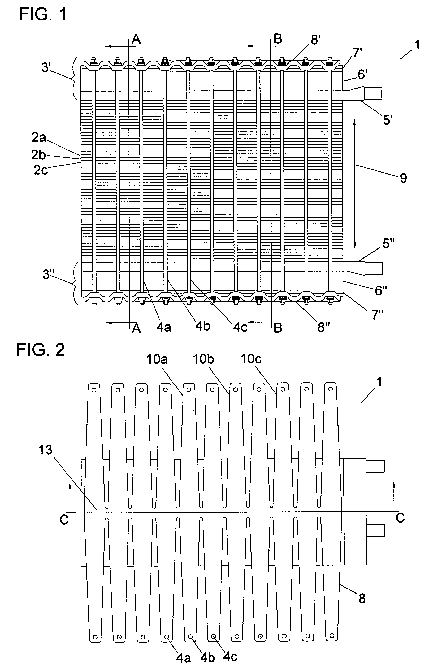
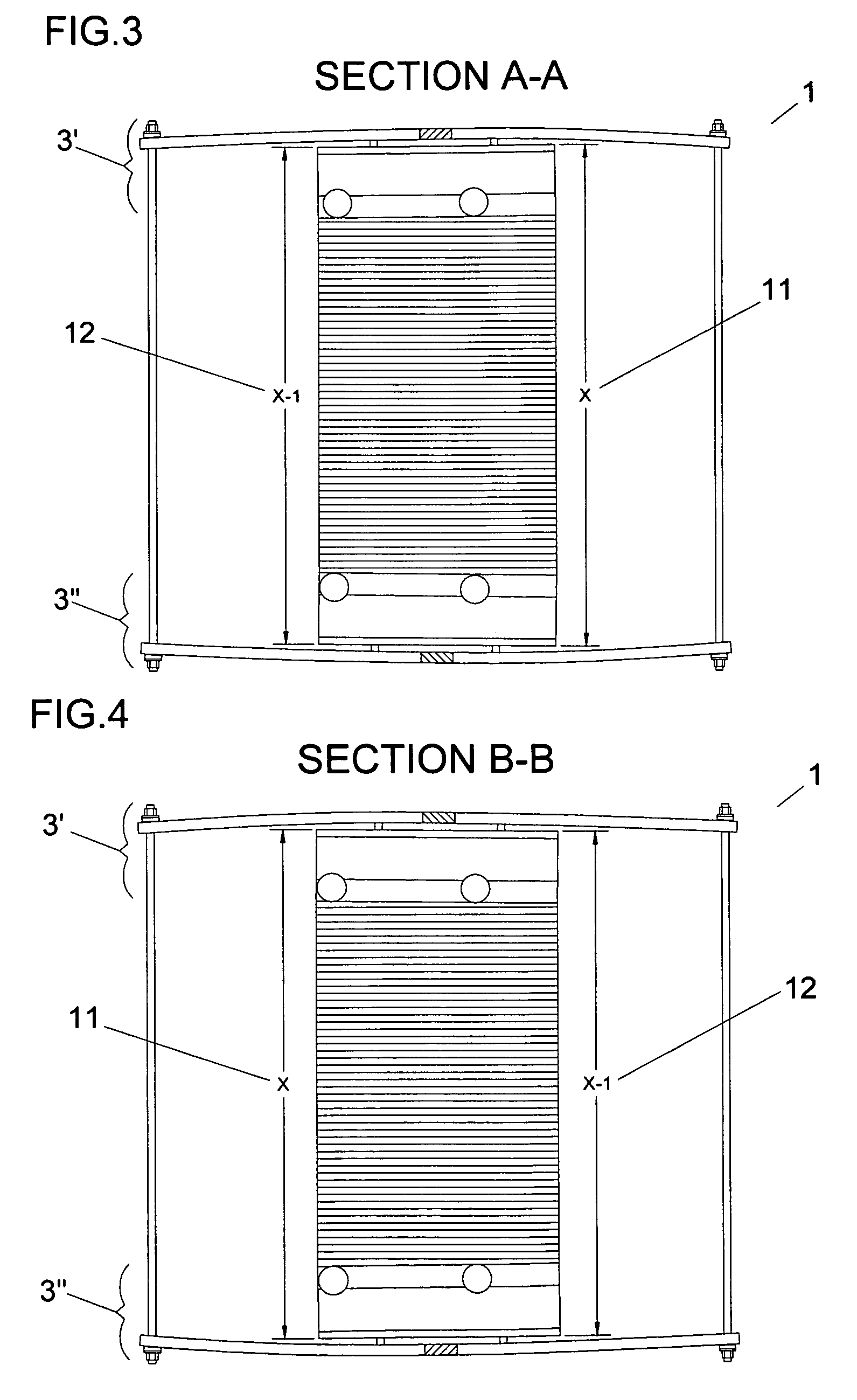
[0029]FIG. 1 illustrates a fuel cell stack 1 such as a fuel cell stack described by U.S. Pat. No. 6,670,069 incorporated herein in its entirety by reference. The fuel cell stack 1 is comprised of a plurality of individual cells 2a, 2b, 2c stacked upon one another. Proper functioning of the individual cells 2a, 2b, 2c requires that they be maintained in intimate and uniform contact at the mating faces of each cell. Uniform contact is typically maintained with the application of opposing compressive loads applied to the axial ends of the fuel cell stack 1 by opposing compression assemblies 3′, 3″ mechanically coupled by a plurality of tie rods 4a, 4b, 4c. Compression assembly 3′ includes end plate manifold 5′, such as the end plate manifold described U.S. patent application Ser. No. 10 / 755,722 incorporated in its entirety by reference, thermal insulation 6′, compression plate 7′ and compression distribution plate 8′.

[0030] During assembly and operation of the fuel cell stack 1, vario...


PUM

PropertyMeasurementUnit
temperaturesaaaaaaaaaa

Abstract

A compression assembly for use with a fuel cell stack is disclosed. The compression assembly includes opposing end plate manifolds, thermal insulation layers, cold compression plates and compression distribution plates. The compression distribution plates include a plurality of extension elements that are connected and in a manner to provide compressive force to the fuel cell stack.

Description

RELATED U.S. APPLICATON(S) [0001] This application claims the benefit of U.S. Provisional Application No. 60 / 652,653 filed on Feb. 14, 2005 and entitled “Fuel Cell Stack Compression Assembly,” the entire disclosure of which is hereby incorporated herein by reference for all purposes.FIELD OF THE INVENTION [0002] This invention relates to fuel cell stacks and to methods and apparatus for the application of compressive load to opposing ends of fuel cell stacks and to methods of mounting fuel cell stacks. BACKGROUND [0003] Fuel cells are electrochemical devices that produce direct electric current and thermal energy. Fuel cell stacks generally include a plurality of fuel cells stacked in a series relationship to achieve higher useable voltage output capacities. Fuel cell stacks are terminated at each end with end plate assemblies. The end plate assemblies are generally equipped by way of tie-rods and plates to apply a compressive load to the fuel cell stack for the purpose of achieving...

Claims


Application Information

Patent Timeline
Patent Type & Authority Applications(United States)
IPC IPC(8): H01M8/02H01M8/24
CPCH01M8/248Y02E60/50
Inventor ALLEN, JEFFREY PETERALLEN, PETER WILCOXOUELLETTE, JAMES L.
Owner CONNECTICUT INNOVATIONS
Why Eureka
Try Eureka