
Underground horizontal rubbish compressor

A garbage compressor and horizontal technology, which is applied in the directions of presses, trash cans, garbage conveying, etc., can solve the problems of affecting the overall horizontal garbage compressor work efficiency, lack of effective guarantee of stability, affecting the subsequent treatment of garbage blocks, etc. The effect of small area, simple structure and comprehensive functions

Inactive Publication Date: 2016-11-16
HEFEI BAIYUN ENVIRONMENTAL SANITARY EQUIP
View PDF6 Cites 11 Cited by
  • Summary
  • Abstract
  • Description
  • Claims
  • Application Information

AI Technical Summary

Problems solved by technology

Commonly used compression methods include horizontal garbage compressors and vertical garbage compressors. For the existing horizontal garbage compressors, first of all, the degree of cooperation with the surrounding environment is not high, and secondly, the uniformity of the garbage after compression and the stability of the compression process Lack of effective protection, it is prone to a series of problems such as local loosening of compressed garbage and extremely uneven compressed garbage blocks; at the same time, there is no targeted design for domestic garbage with high water content, resulting in the compressed water remaining in the compressed In the cavity, on the one hand, it affects the follow-up treatment of the compressed garbage block, and on the other hand, it also affects the normal operation of the compressor; again, the pressure head of the existing compressor often slides through the slider and the chassis, and the matching is not high. Serious wear and tear in long-term operation affects the efficiency of the overall horizontal garbage compressor

Method used


Image

  • Underground horizontal rubbish compressor

Examples


Embodiment Construction

[0008] Below in conjunction with specific embodiment, preparation method of the present invention is described in further detail:

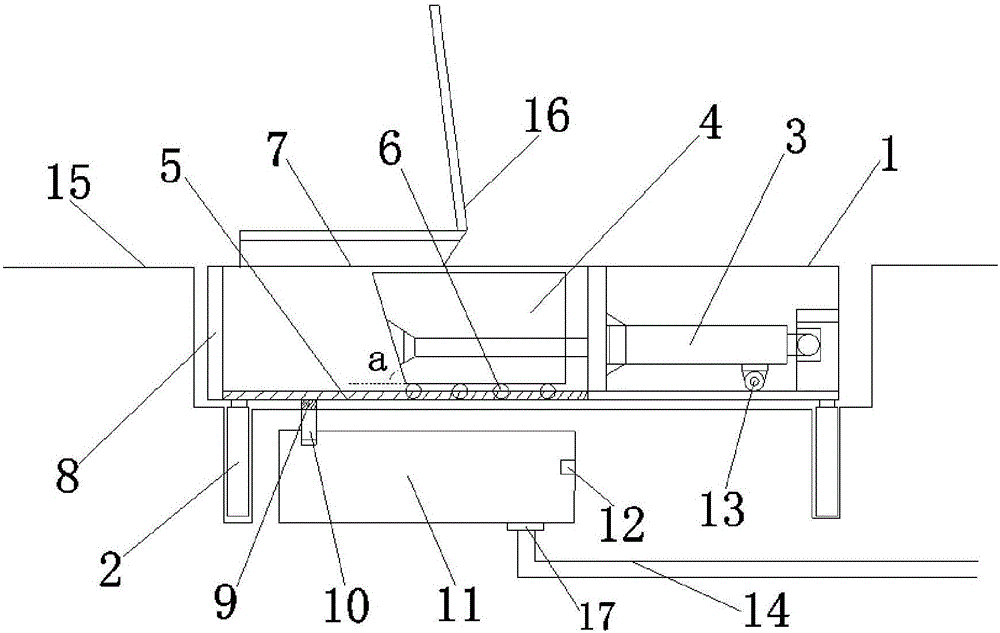
[0009] refer to figure 1 The shown underground horizontal garbage compressor includes a cabinet 1, four lifting cylinders 2 are arranged at the bottom of the cabinet 1, and the cabinet 1 and the lifting cylinders 2 are fixed in a pit 15, and the upper end of the cabinet is connected to the ground level.

[0010] Described chassis 1 is provided with master oil cylinder 3, and the cylinder body of described master oil cylinder 3 is fixed on the right end of chassis 1, and the load-bearing wheel 13 that is used to support cylinder body is connected with support below the cylinder body, and load-bearing wheel 13 is not easy to take place due to gravity. Bend for longer life.

[0011] The piston rod end of the main oil cylinder 3 is fixed with a pressure head 4, the angle a between the compression surface of the pressure head 4 and the bottom surface...


PUM


Abstract

The invention discloses an underground horizontal garbage compressor, comprising a machine case, four lifting oil cylinders are arranged at the bottom of the machine case, the machine case and the lifting oil cylinders are fixed in a pit, and the upper end of the machine case is level with the ground; There is a main oil cylinder inside, and the cylinder body of the main oil cylinder is fixed on the right end of the chassis. The load-bearing wheels for supporting the cylinder body are connected under the cylinder body through a bracket. The piston rod end of the main oil cylinder is fixed with a pressure head. The angle between the compression surface of the head and the bottom surface of the chassis is an acute angle; at least two rollers are symmetrically installed on both sides of the lower end of the pressure head, and two slide rails are correspondingly provided on both sides of the chassis, and the rollers and the slide rails are movable Connection; the garbage compressor of the present invention has comprehensive functions and simple structure, adopts an underground installation structure, has strong adaptability to the surrounding environment, and has higher work efficiency.

Description

technical field [0001] The invention relates to the technical field of garbage compression, in particular to an underground horizontal garbage compressor. Background technique [0002] At present, with the country's continuous emphasis on environmental protection and the improvement of people's living standards, in order to prevent garbage from polluting the surrounding environment, garbage needs to be pretreated by transfer equipment, which needs to be efficient and low-cost. Commonly used compression methods include horizontal garbage compressors and vertical garbage compressors. For the existing horizontal garbage compressors, first of all, the degree of cooperation with the surrounding environment is not high, and secondly, the uniformity of the garbage after compression and the stability of the compression process Lack of effective protection, it is prone to a series of problems such as local loosening of compressed garbage and extremely uneven compressed garbage blocks...

Claims


Application Information

Patent Timeline
Patent Type & Authority Applications(China)
IPC IPC(8): B65F9/00
CPCB30B9/3042B30B9/3039B65F1/1405B65F1/1447B65F2210/132B65F9/00
Inventor 吴登峰
Owner HEFEI BAIYUN ENVIRONMENTAL SANITARY EQUIP
Learn More