Biochip cartridge and biochip reader

a biochip and reader technology, applied in the field of biochips and biochip readers, can solve the problems of limited light that can be received, difficult alignment between multibeams and sites, etc., and achieve the effect of increasing the amount of received ligh

Active Publication Date: 2009-07-14
YOKOGAWA ELECTRIC CORP
View PDF10 Cites 3 Cited by
  • Summary
  • Abstract
  • Description
  • Claims
  • Application Information

AI Technical Summary

Benefits of technology

[0012]An object of the invention is to provide a biochip cartridge and a biochip reader for increasing the received light amounts and eliminating the need for performing alignment between multibeam and site.
[0014]According to the biochip cartridge, fluorescence from each site also passes through the microlens for applying exciting light to the site, and fluorescence generated at a wide divergence angle from the site can be collected efficiently. Thus, an image with large numerical aperture and large light amount can be provided.
[0018]In the biochip cartridge, the sites may be attached to a back surface of the lid portion. In this case, fluorescence can be collected efficiently on the microlenses with no buffer liquid.
[0020]According to the biochip reader, the biochip reader for producing similar effects to those of the biochip cartridge can be easily provided.
[0022]According to the biochip cartridge and the biochip reader, the following advantages are provided:
[0023](1) Buffer liquid is filled into the hollow portion of the cartridge, whereby a wet optical system equivalent to an oil immersion lens or a water immersion lens can be provided and numerical aperture NA can be taken large, so that a bright image with a large light amount can be easily provided.

Problems solved by technology

However, the biochip reader in the related art involves the following problems:(1) Air is involved in optical system and the amount of light that can be received is limited.(2) It is difficult to perform alignment between multibeam and site.

Method used


Image

  • Biochip cartridge and biochip reader
  • Biochip cartridge and biochip reader
  • Biochip cartridge and biochip reader

Examples


Embodiment Construction

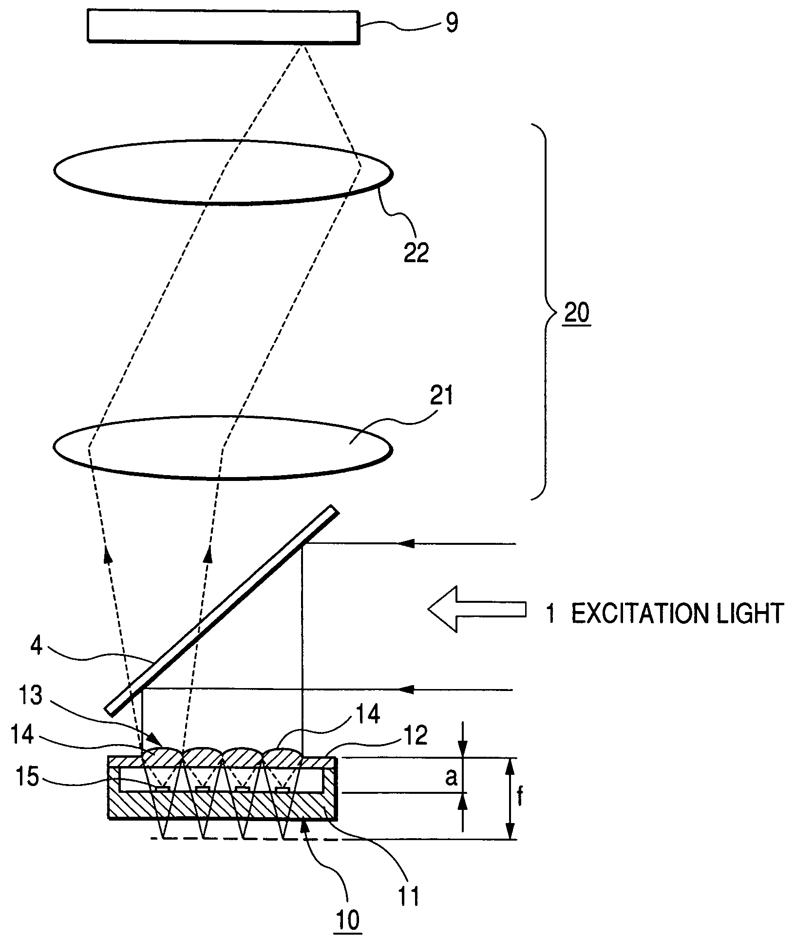
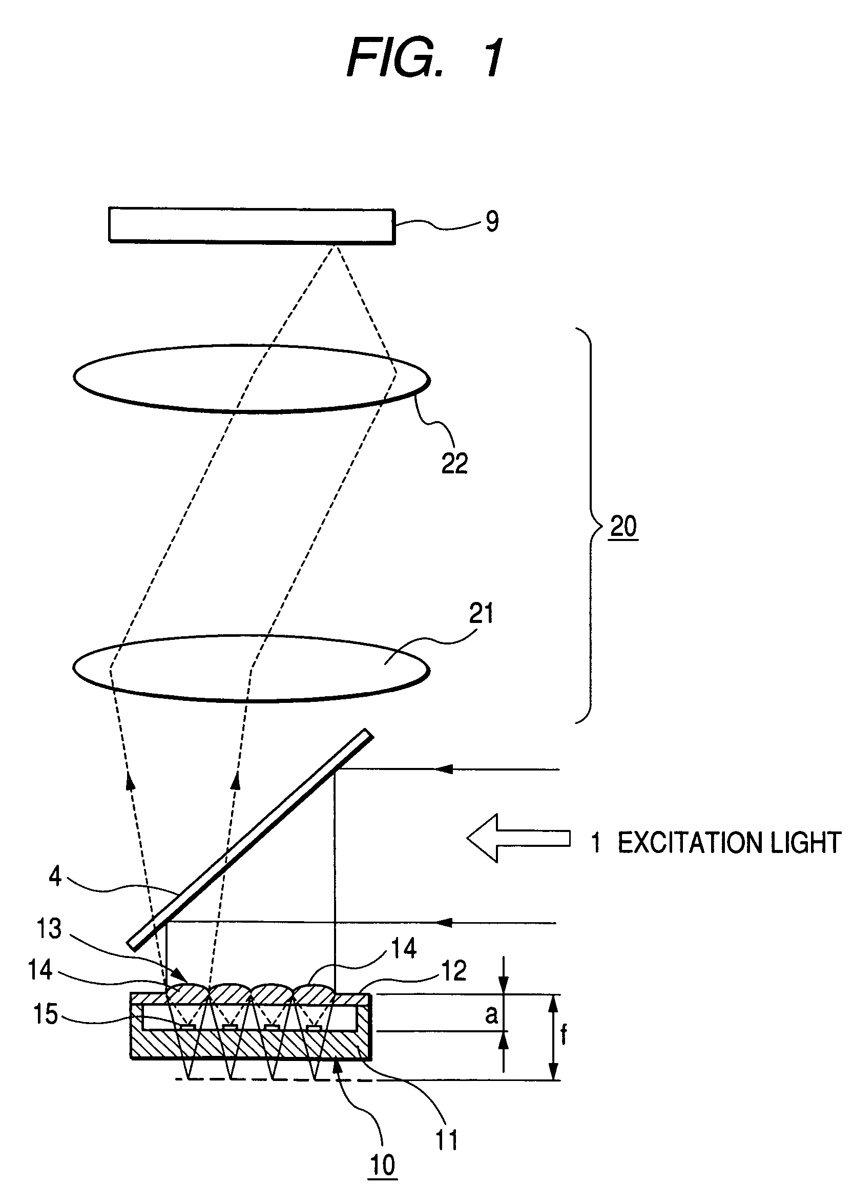
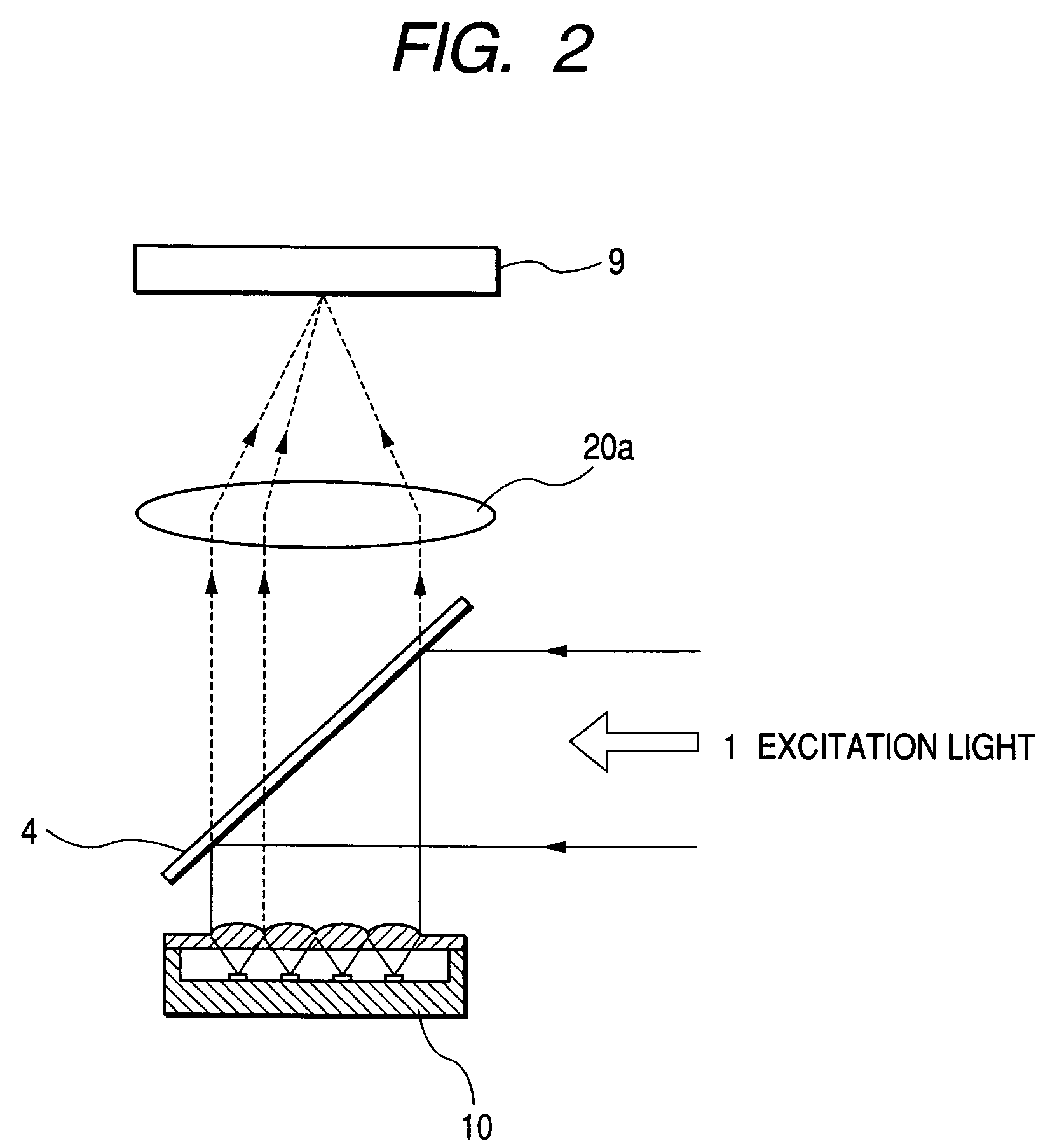
[0031]Embodiments of the invention will be discussed in detail with the accompanying drawings. FIG. 1 is a drawing of the configuration of the main part to show an embodiment of a scanless (non-optically-scanned) biochip reader according to the invention. Parts identical with those previously described with reference to FIG. 6 are denoted by the same reference numerals in FIG. 1. In FIG. 1, numeral 10 denotes a cartridge and numeral 20 denotes a relay lens having a first lens 21 and a second lens 22.

[0032]The cartridge 10 has a box-like vessel 11 and a lid portion 12. The lid portion 12 has a microlens array 13 including a plurality of microlenses 14 for collecting excitation light and fluorescence. The microlens array 13 is formed integrally with the lid portion 12. Sites 15 of a biochip are provided on the internal bottom of the vessel 11. The sites 15 are disposed at the same pitches as the microlenses so that excitation light applied to the site 15 and fluorescence generated fro...


PUM

PropertyMeasurementUnit
fluorescenceaaaaaaaaaa
sizeaaaaaaaaaa
optical axisaaaaaaaaaa

Abstract

A biochip cartridge has a vessel and a lid portion having a plurality of microlenses. A biochip having a plurality of sites is provided in the vessel. The plurality of sites are to be disposed at the same pitches as the microlenses. Excitation light is applied to each of the sites through each microlens corresponding to each site, and fluorescence generated from each site passes through a microlens corresponding to each site.

Description

CROSS-REFERENCE TO RELATED APPLICATIONS[0001]This application is based upon and claims the benefit of priority from the prior Japanese Patent Applications No. 2004-237856 filed on Aug. 18, 2004, the entire contents of which are incorporated herein by reference.BACKGROUND OF THE INVENTION[0002]1. Field of the Invention[0003]This invention relates to a biochip and a biochip reader for applying a plurality of excitation light beams to a plurality of sites of a biochip at the same time.[0004]2. Description of the Related Art[0005]A biochip reader for applying a plurality of excitation light beams to a plurality of sites of a biochip at the same time and observing a specimen at each site is available. (For example, refer to JP-A-2002-207007.)[0006]FIG. 6 is a drawing to show a configuration example of a biochip reader designed to read image information of a plurality of specimens by a non-scanning method, described in JP-A-2002-207007. In the figure, light from a light source 1 becomes c...

Claims


Application Information

Patent Timeline
Patent Type & Authority Patents(United States)
IPC IPC(8): C12M1/34C12M1/00
CPCG01N21/0303G01N21/6486G01N21/6456G01N21/6452
Inventor TANAAMI, TAKEO
Owner YOKOGAWA ELECTRIC CORP
Why Eureka
Try Eureka