
Audio signal processing device

a signal processing and audio technology, applied in the direction of electrical transducers, gain control, instruments, etc., can solve the problems of many settings being changed, the operator's grasp is difficult, and it is difficult to grasp the presence or absence of change, and it is difficult to memorize all,

Inactive Publication Date: 2009-07-14
YAMAHA CORP
View PDF9 Cites 23 Cited by
  • Summary
  • Abstract
  • Description
  • Claims
  • Application Information

AI Technical Summary

Benefits of technology

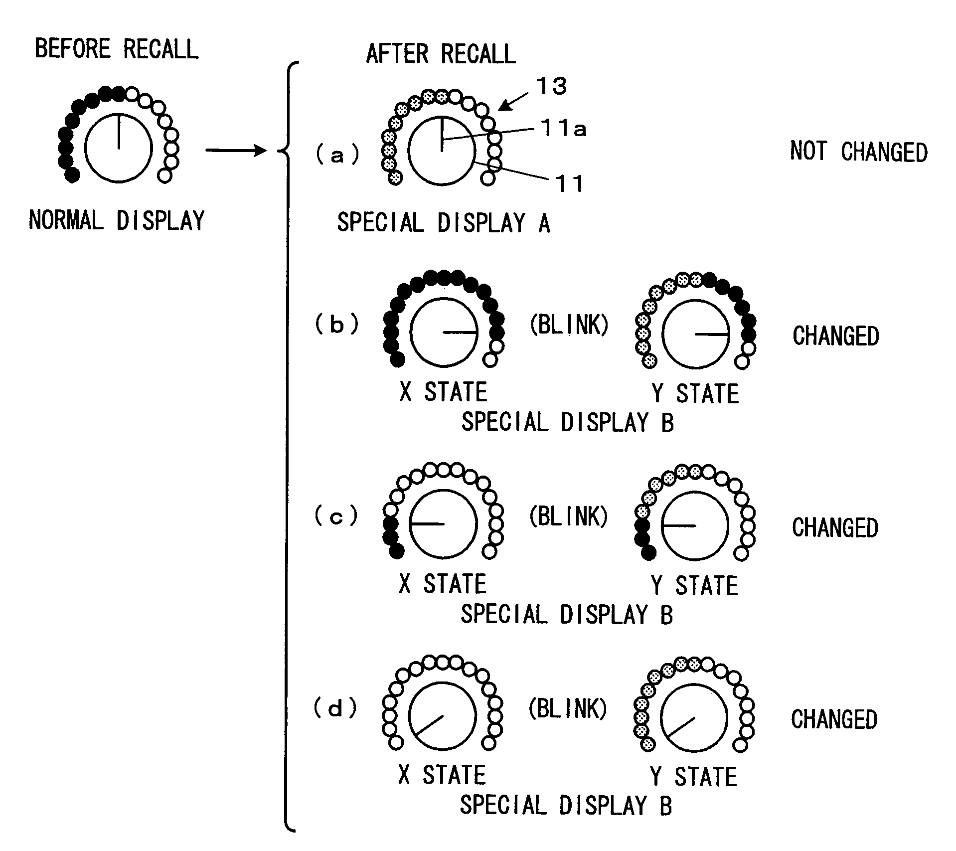
[0012]It is an object of the present invention to solve the above-described problems and to configure an audio signal processing device which processes audio signals and outputs the audio signals such that when a value of a parameter stored therein is loaded, part of the value of the parameter changed from the value at the time of the loading and part thereof not changed can be easily distinguished.

Problems solved by technology

However, there has been a problem at the time when many settings are changed in an instant such as when the scene data is recalled.
More specifically, in such a case, the values of the parameters before the recall will be displayed before the recall and the values of the parameters relating to the recalled scene data will be displayed after the recall, but there has been a problem that it is difficult for the operator to grasp, even taking a look at the display after the recall, how and what parameters were changed by the recall of the scene data.
Although it is possible to have some grasp by comparison between the displays before and after the recall, typically the controls are considerably large in number in the digital mixer, and therefore it is considerably difficult to grasp the presence or absence and the degree of change and memorize all of them at the instant of the recall.
The operation, however, is troublesome and time consuming and, in addition, once the scene data is reflected in the signal processing, the operator needs to remember the changed parts.
In an actual use of the digital mixer, it has been often performed that a plurality of scene data with the values of only a part among many parameters being changed are created and recalled in sequence for use, and there has been a strong demand to grasp where the values of the parameters relating to the recalled scene data are different from the values set before the recall, but the conventional digital mixers could not sufficiently meet the demand as described above.

Method used


Image

  • Audio signal processing device
  • Audio signal processing device
  • Audio signal processing device

Examples


Embodiment Construction

[0031]Hereinafter, preferred embodiments of the invention will be described with reference to the drawings.

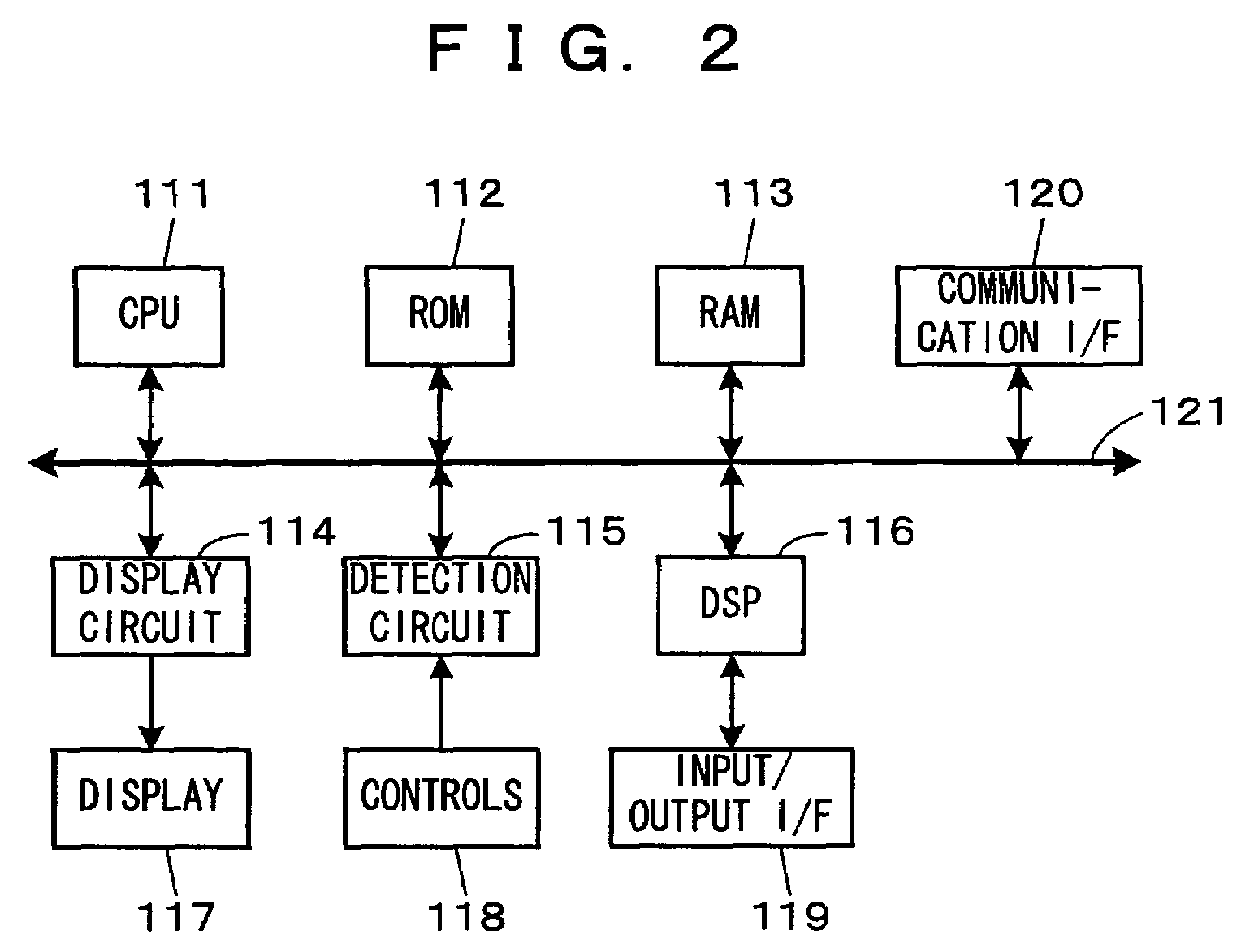
[0032]A configuration of a digital mixer being an embodiment of an audio signal processing device according to the invention will be described first. FIG. 2 is a block diagram showing the configuration of the digital mixer.

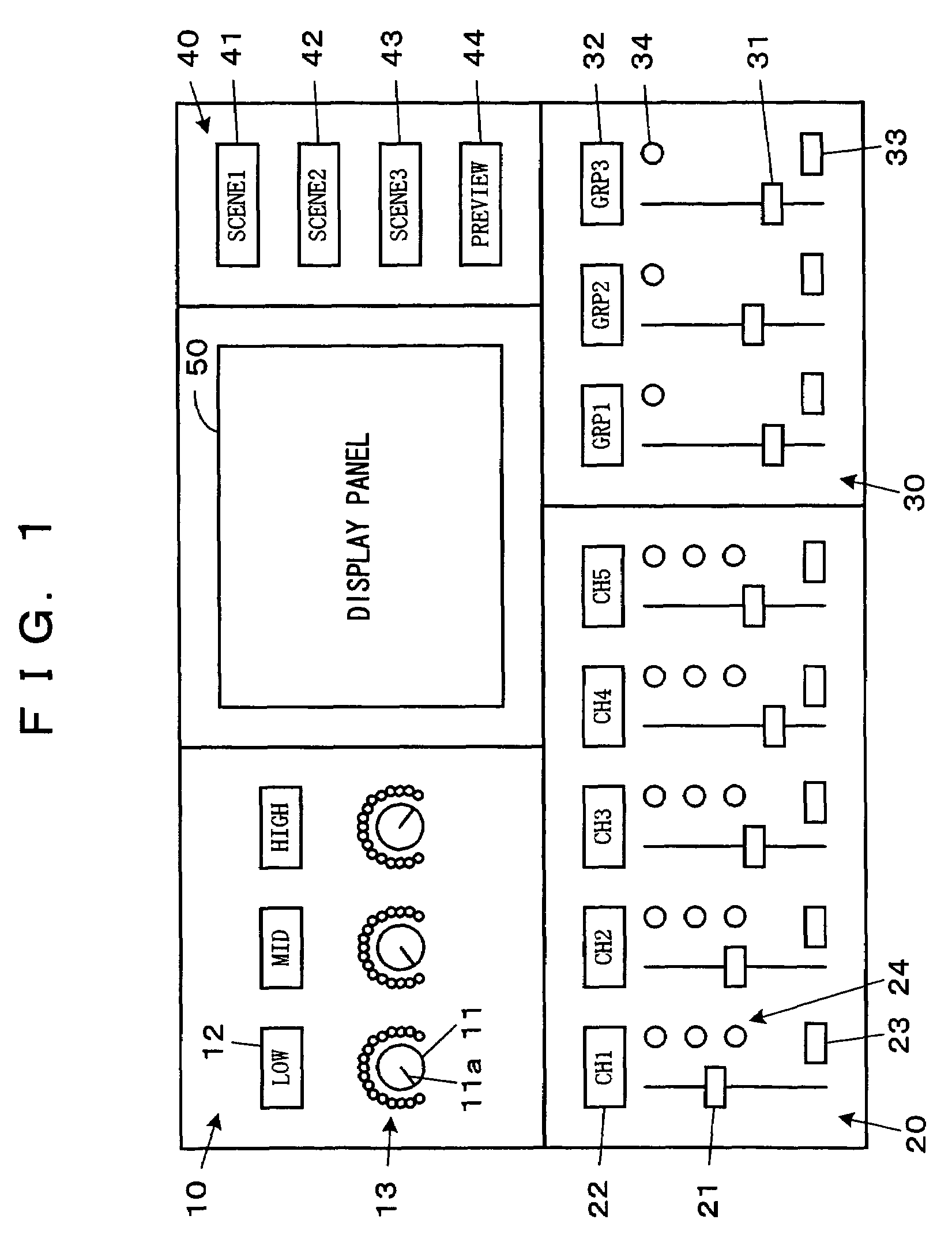
[0033]The digital mixer (hereafter, also referred to simply as a “mixer”) is an audio signal processing device which performs various kinds of signal processing such as mixing, equalizing, and so on for inputted audio signals in accordance with set parameters and outputs the audio signals, in which, as shown in FIG. 2, a CPU 111, a ROM 112, a RAM 113, a display circuit 114, a detection circuit 115, a digital signal processor (DSP) 116, and a communication interface (I / F) 120 are connected to a system bus 121. Further, a display 117, controls 118, and an input / output I / F 119 are connected to the display circuit 114, detection circuit 115, DSP116, respectively....


PUM


Abstract

In an audio signal processing device which processes audio signals and outputs the audio signals, setting controls, such as filter controls, for setting values of parameters for the signal processing and a display for presenting information by the presence or absence and the style of lighting of LEDs is provided, in which when scene data stored in a scene memory is loaded, the display style of the display is made different in accordance with match / mismatch between a current set value of the parameter and the value of the parameter relating to the loaded scene data. Alternatively, the display is made to simultaneously present the loaded value and the value at the time of the loading in different display styles.

Description

BACKGROUND OF THE INVENTION[0001]1. Field of the Invention[0002]The present invention relates to an audio signal processing device which processes audio signals and outputs the audio signals and, more particularly, to an audio signal processing device characterized by control of display on a display portion. Further, the invention relates to a program for making a computer controlling the audio signal processing device perform such a control.[0003]2. Description of the Related Art[0004]Conventionally, in an audio signal processing device such as a digital mixer which processes audio signals and outputs the audio signals, indicators have been provided near corresponding setting controls for setting values of parameters for the signal processing to display the values of the parameters set by the controls (see U.S. 2002 / 0156547 A1, particularly FIG. 8 of the drawings and section 0061 in the description).[0005]As the aforementioned indicator, an indicator is used that presents informati...

Claims


Application Information

Patent Timeline
Patent Type & Authority Patents(United States)
IPC IPC(8): G06F17/00G06F3/00H04B1/00H04R3/00
CPCH04H60/04
Inventor TERADA, KOTAROOTA, MITSUHIKO
Owner YAMAHA CORP
Learn More