Hands-free level indicating device

a level indicator and hand-free technology, applied in the field of levels, can solve the problems of inability to operate with one person, inconvenient manufacturing, and inconvenient use of magnets for attaching to non-magnetic materials, and achieve the effects of long operating life, quick and removable attachment, and economical manufactur

Active Publication Date: 2009-07-21
GENTLEMAN CARL +2
View PDF16 Cites 17 Cited by
  • Summary
  • Abstract
  • Description
  • Claims
  • Application Information

AI Technical Summary

Benefits of technology

[0014]More specifically, an object of the present invention is to provide an apparatus that can be quickly and removably attached to a conventional level, that has a hook-shaped portion for attaching to non-magnetic structural members, that can be used with different sizes of structural members, and that is economical to manufacture and capable of a long operating life.
[0015]To achieve these and other objects of the invention, a hands-free level indicating device is provided that includes a level for determining a spatial orientation of a structural member, and an apparatus for securing the level to the structural member. The apparatus includes a U-shaped portion for attaching to the level and a hook-shaped portion for clamping around the structural member. The U-shaped portion and hook-shaped portion can be formed from a single strip of flat material, such as spring steel. A spring is provided to bias the hook-shaped portion in a direction toward the level to allow the apparatus to secure the level to different sizes of structural members. The spring can be a leaf spring that attaches to a base of the U-shaped portion and extends in a longitudinal direction of the level.

Problems solved by technology

However, a single person operation is not always feasible due to the awkward handling characteristics of the structural member to be positioned.
However, the magnets are not useful for attaching to non-magnetic materials, such as PVC, CPVC, aluminum, magnesium, wood, and the like.

Method used


Image

  • Hands-free level indicating device
  • Hands-free level indicating device
  • Hands-free level indicating device

Examples


Embodiment Construction

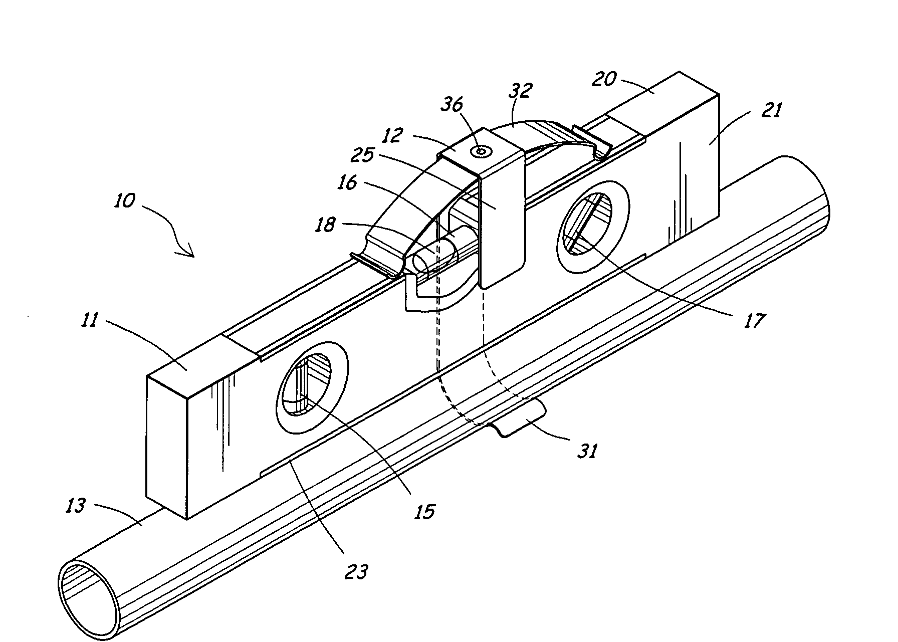
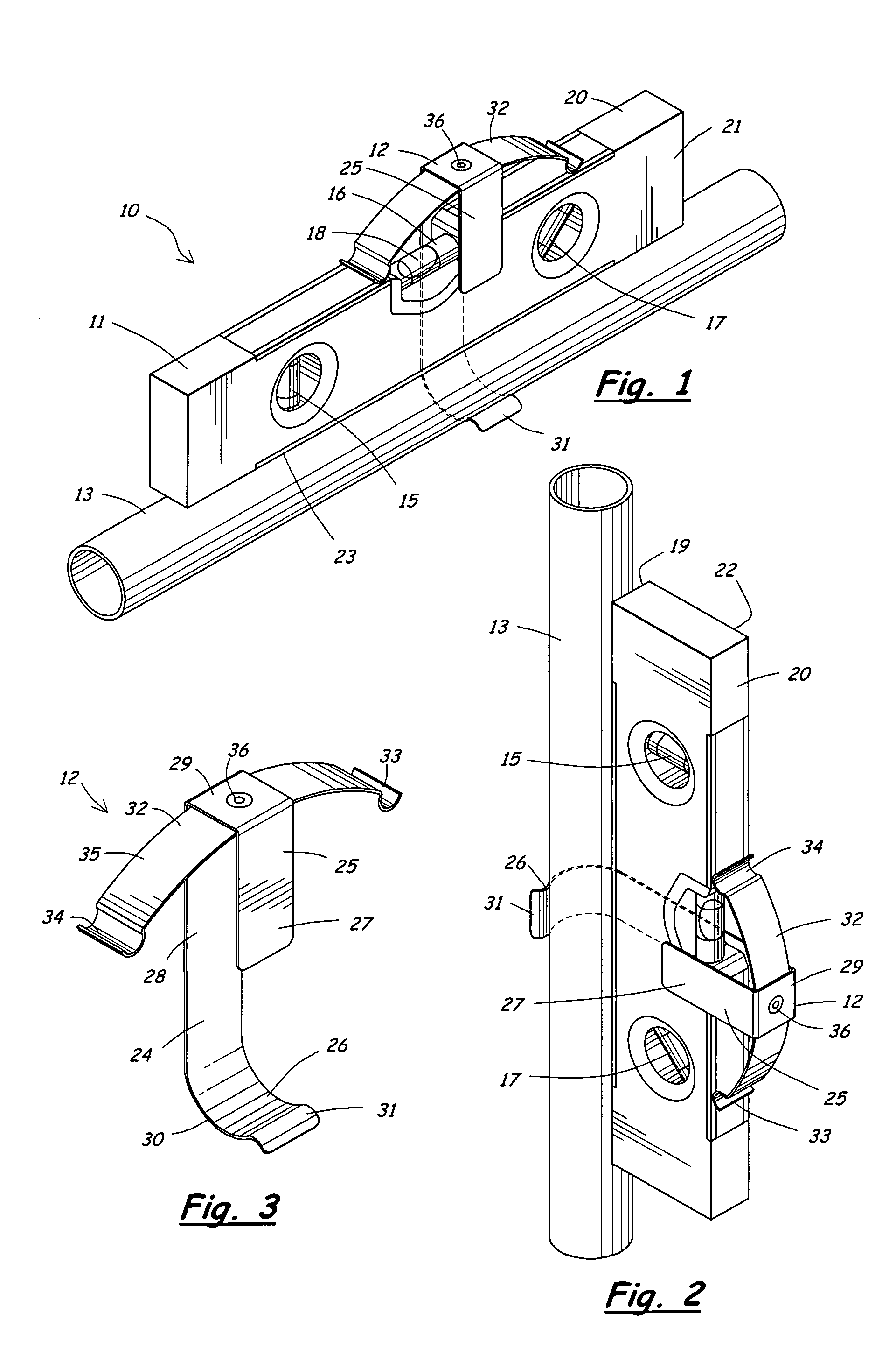
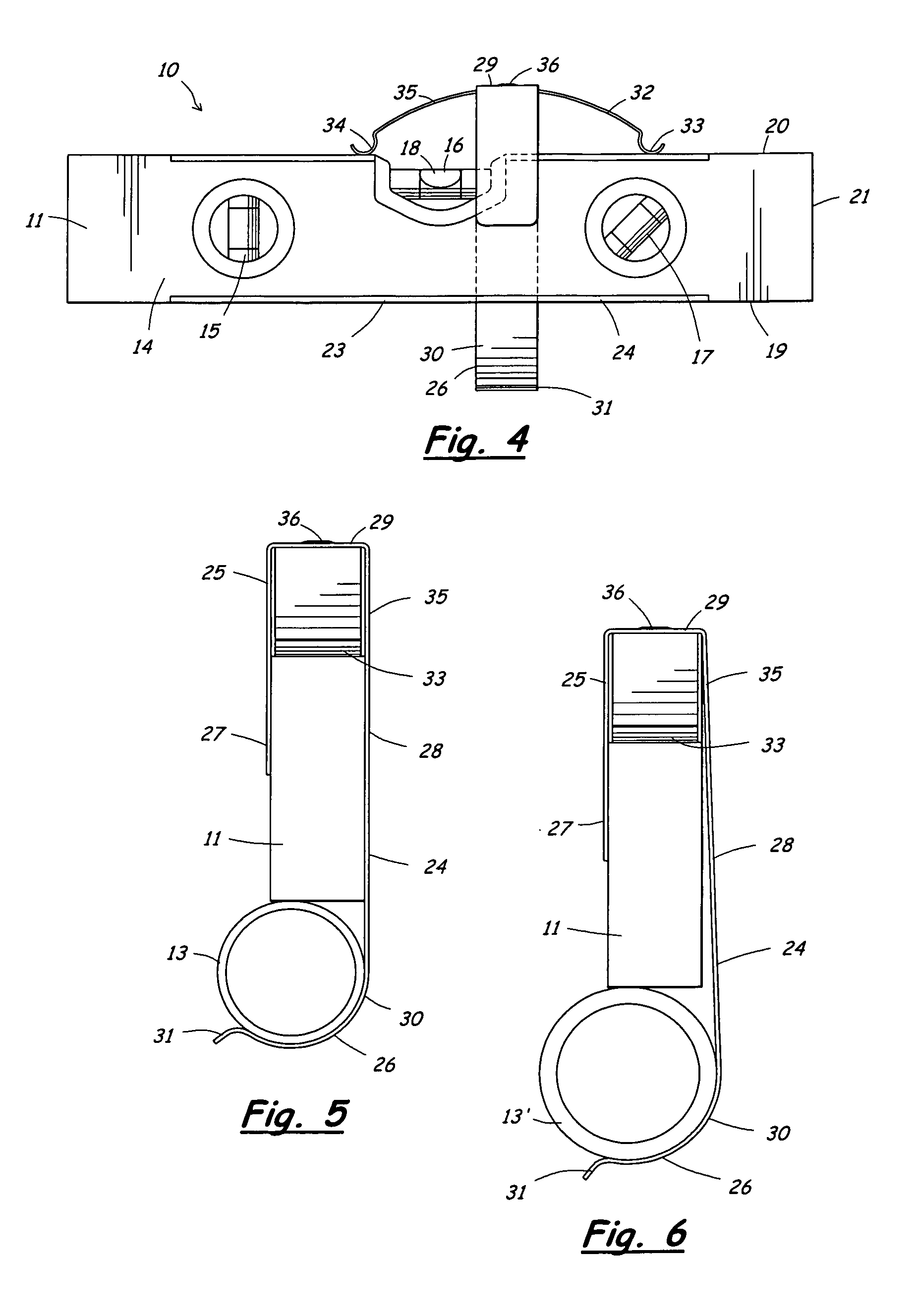
[0027]A hands-free level indicating device 10 according to the present invention will now be described in detail with reference to FIGS. 1 to 7 of the accompanying drawings.

[0028]The hands-free level indicating device 10 of the present invention comprises a level 11 and an apparatus 12 for securing the level 11 to a structural member 13. The level 11 can be, for example, a conventional level used by carpenters, electricians, plumbers and other craftsman. The level 11 includes a body 14 having one or more liquid-filled tubes 15-17 inset therein. An air bubble 18 in each tube provides a visual indication of the spatial orientation of the tube 15.

[0029]The level shown in FIG. 1 has three liquid-filled tubes 15-17 mounted thereon at various orientations, including a first tube 15 extending in a transverse direction, a second tube 16 extending in a longitudinal direction, and a third tube 17 extending at a 45 degree angle. The tubes 15-17 of the level 11 are arranged in different directi...


PUM


Abstract

A hands-free level indicating device includes a level for determining a spatial orientation of a structural member, and an apparatus for securing the level to the structural member. The apparatus includes a U-shaped portion for attaching to the level and a hook-shaped portion for clamping around the structural member. The U-shaped portion and hook-shaped portion can be formed from a single strip of flat material, such as spring steel. A spring is provided to bias the hook-shaped portion in a direction toward the level to allow the apparatus to secure the level to different sizes of structural members. The spring can be a leaf spring that attaches to a base of the U-shaped portion and extends in a longitudinal direction of the level.

Description

RELATED APPLICATIONS[0001]This application claims priority of U.S. Provisional Application No. 60 / 874,367 filed on Mar. 28, 2007. The entire content of this prior application is hereby incorporated by reference.BACKGROUND OF THE INVENTION[0002]1. Field of the Invention[0003]This invention relates generally to levels and, in particular, to an apparatus for securing a level to a structural member for hands-free use of the level.[0004]2. Description of the Related Art[0005]Carpenters, plumbers, electricians, and other craftsmen work with structural members, such as pipes, rods and beams in the construction industry. Typical construction operations include fixing structural members in a predetermined spatial orientation, such as horizontal, vertical, or pitched. A level is used to align the structural members in the desired horizontal, vertical, or pitched spatial orientation.[0006]A conventional level includes a working surface along one side edge, and a body containing one or more tra...

Claims


Application Information

Patent Timeline
Patent Type & Authority Patents(United States)
IPC IPC(8): G01C9/26
CPCG01C9/28Y10T24/44855Y10T24/44923
Inventor GENTLEMAN, CARLHINZE, ROBERT E.TSCHANTRE, DARYL L.
Owner GENTLEMAN CARL
Why Eureka
Try Eureka