Determination of density for metering a fluid flow

a technology of density measurement and fluid flow, applied in the direction of liquid/fluent solid measurement, volume metering, instruments, etc., can solve the problems of difficult prediction of losses, introduction of significant errors in density measurement, etc., to enhance the displacement of liquid, increase centrifugal acceleration, and increase centrifugal acceleration

Inactive Publication Date: 2009-07-21
SCHLUMBERGER TECH CORP
View PDF32 Cites 21 Cited by
  • Summary
  • Abstract
  • Description
  • Claims
  • Application Information

AI Technical Summary

Benefits of technology

[0012]Measuring the pressure difference in a direction perpendicular to the flow direction has an advantage in that the frictional pressure loss caused by the measurement will generally be zero. Frictional pressure losses can be difficult to predict, in particular for multiphase flows, and can introduce significant errors in density measurements.
[0062]Although in use the passages extend substantially horizontally across the wall of the conduit, each passage may extend initially from its inner opening in a direction which is perpendicular to that part of the internal face of the wall where the inner opening is located. Typically, this results in a short section of passage which is non-horizontal, or even vertical. When the section of conduit conveys a swirling flow of gas-liquid mixture, the liquid at the wall will have a substantial circumferential velocity component. However, by having the passage extend initially from the inner opening in a direction which is perpendicular to the internal face of the wall, this velocity component is prevented from forcing liquid from the swirling flow directly into the passages.

Problems solved by technology

Frictional pressure losses can be difficult to predict, in particular for multiphase flows, and can introduce significant errors in density measurements.

Method used


Image

  • Determination of density for metering a fluid flow
  • Determination of density for metering a fluid flow
  • Determination of density for metering a fluid flow

Examples


Embodiment Construction

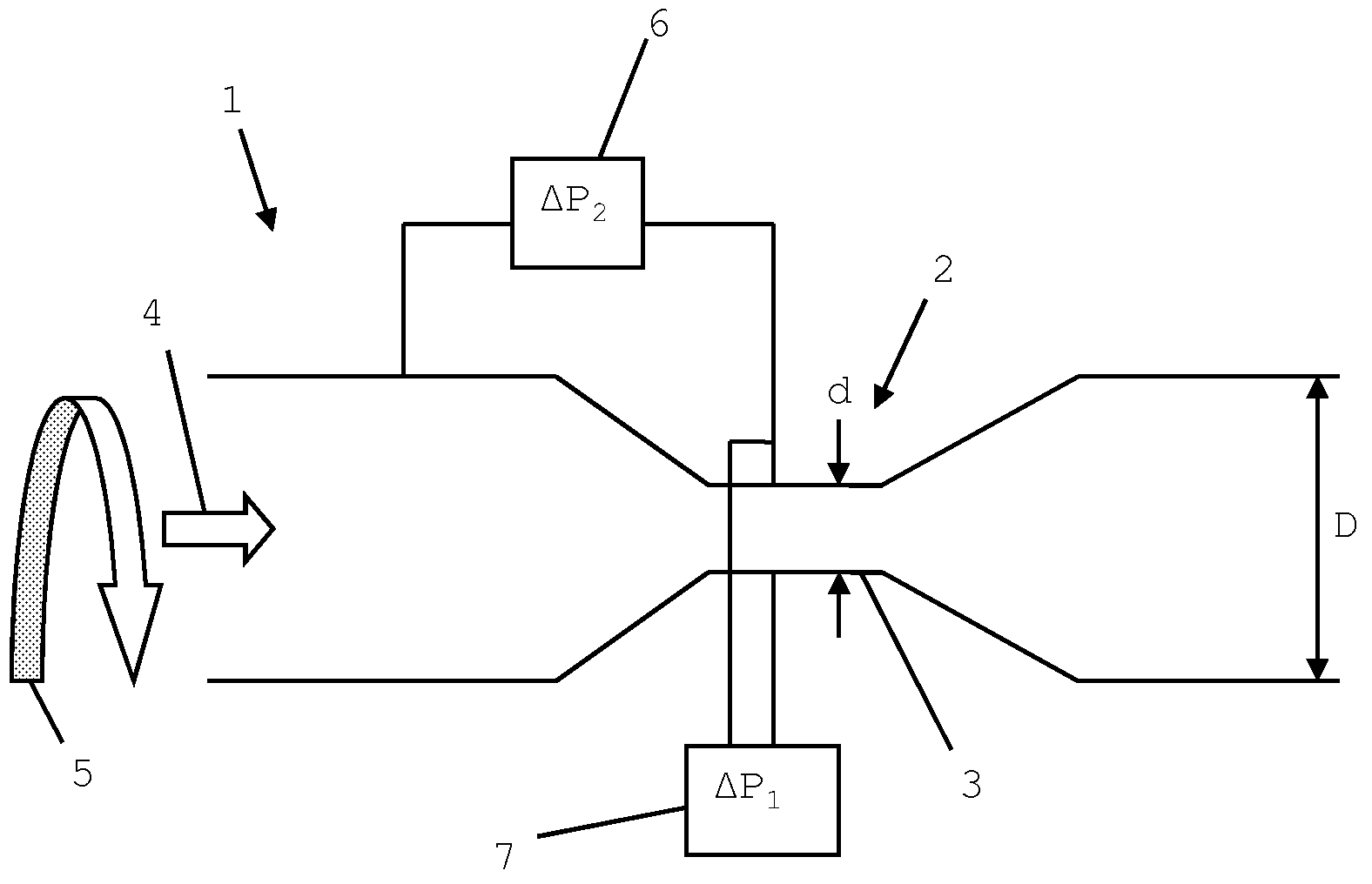
[0070]FIG. 1 shows schematically a longitudinal section through a first embodiment of an apparatus for providing measurements useable in determining a flow rate of a gas-liquid fluid mixture.

[0071]The apparatus comprises a substantially horizontal conduit 1 of circular cross-section. The conduit has a Venturi 2, the throat 3 of the Venturi providing a constriction region in the conduit.

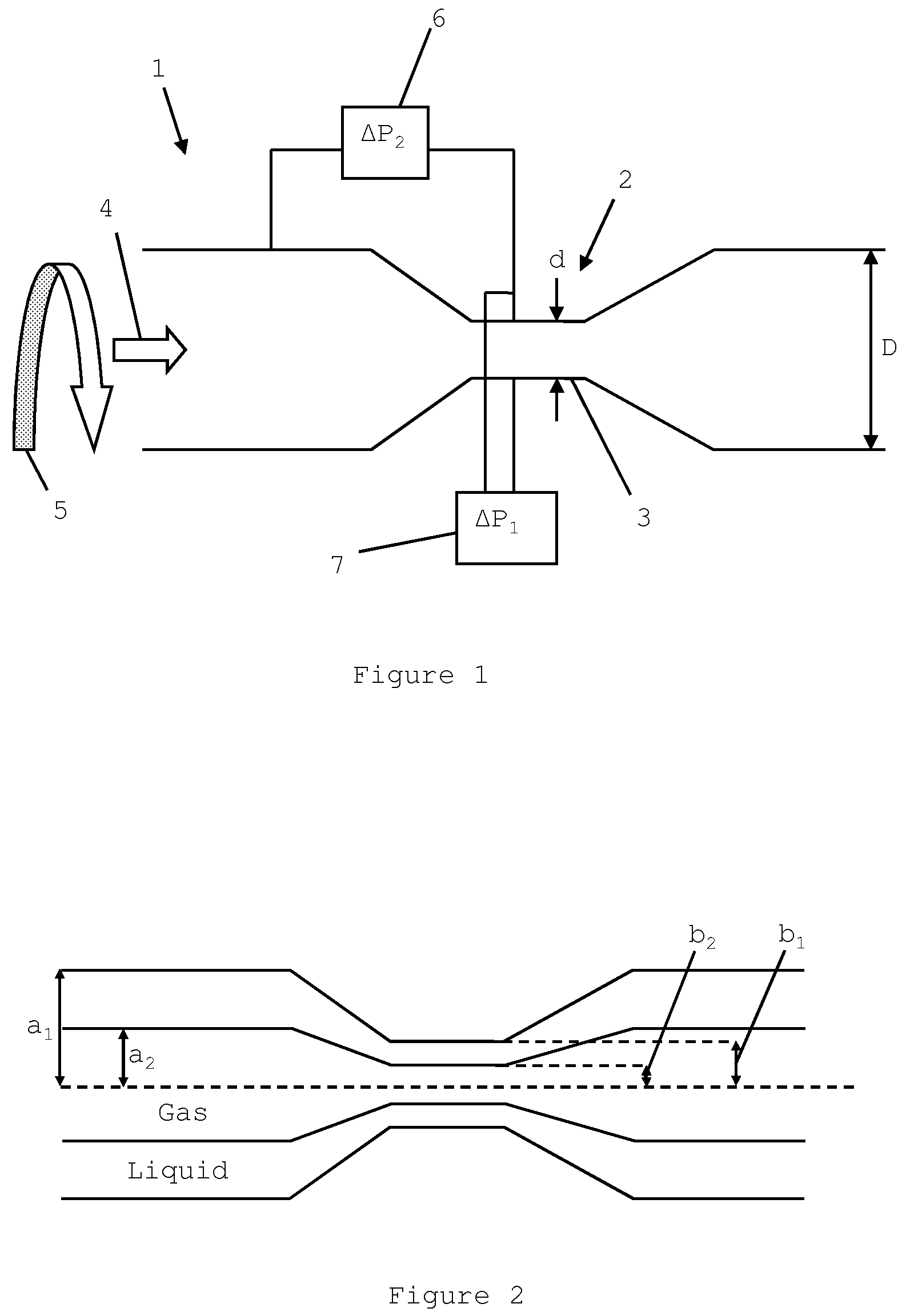
[0072]A gas-liquid fluid mixture flows through the conduit in the direction indicated by arrow 4. A swirl element (not shown) induces the mixture to exhibit swirling flow as indicated by arrow 5. An effect of this swirling flow is that liquid from the mixture is displaced to the wall of the conduit to form a liquid annulus around a gas core, shown schematically in FIG. 2. In the throat of the Venturi, centrifugal acceleration enhances the displacement of liquid to the wall of the conduit.

[0073]Returning to FIG. 1, on a transverse cross-section at the Venturi throat, a first pressure meter 7 measures t...


PUM


Abstract

Systems and methods are disclosed for measuring densities and flow rates of gas-liquid fluid mixtures. In the systems and methods, the fluid mixture is caused to exhibit swirling flow as it flows through a conduit that includes a constriction, a first pressure difference is measured between two vertically-spaced measurement positions in the conduit, a second pressure difference is measured between two horizontally-spaced measurement positions in the conduit, the first horizontally-spaced measurement position being at the constriction region and the second horizontally-spaced measurement position being upstream or downstream of the constriction region, and one or more of the pressure differences is used to determine a density or a flow rate of the gas-liquid fluid mixture.

Description

CROSS-REFERENCE TO RELATED APPLICATIONS[0001]The present application claims priority under 35 U.S.C. §119 to Great Britain Application No. 0721636.9, filed on Nov. 3, 2007, naming Atkinson et al. as inventors, which is incorporated herein by reference in its entirety for all purposes.FIELD OF THE INVENTION[0002]The present invention relates to a method of measuring the density of fluid flow, and more particularly to a method of measuring the flow rate of a gas-liquid fluid mixture.BACKGROUND OF THE INVENTION[0003]The determination of gas and liquid flow rates and mixture densities in gas-liquid fluid mixtures is important in the oil and gas industry.[0004]An example of an apparatus for measuring such flow rates is Schlumberger's Vx™ system (see e.g. I. Atkinson, M. Berard, B.-V. Hanssen, G. Ségéral, 17th International North Sea Flow Measurement Workshop, Oslo, Norway 25-28 October 1999 “New Generation Multiphase Flowmeters from Schlumberger and Framo Engineering AS”) which comprises...

Claims


Application Information

Patent Timeline
Patent Type & Authority Patents(United States)
IPC IPC(8): G01F1/44
CPCG01F1/44G01N9/26G01F1/74G01F15/00G01F1/34G01F1/40G01F1/88
Inventor ATKINSON, IANSHERWOOD, JOHN
Owner SCHLUMBERGER TECH CORP
Why Eureka
Try Eureka