Device for receiving and separating chips and cooling liquid discharged from machine tools (drive)

a technology of machine tools and cooling liquid, which is applied in the direction of filtration separation, separation processes, manufacturing tools, etc., can solve the problems of increasing wear on these bearings, and achieve the effect of increasing the circumferential speed

Inactive Publication Date: 2009-07-21
MAYFRAN INT BV
View PDF19 Cites 4 Cited by
  • Summary
  • Abstract
  • Description
  • Claims
  • Application Information

AI Technical Summary

Benefits of technology

[0004]The object of the present invention, then, is to reduce the bearing load of the filter drum in a device of the type mentioned at the beginning and to make it possible for a filter cake to form on the outside on the circumference of the drum despite a continuously revolving transport element, this filter cake positively influencing the filter effect.
[0006]In this case, the pressure exerted during the deflection of the transport element in the region of the filter drum is absorbed by the guide rails and the bearings of this drum are relieved. At the same time, the filter drum does not automatically follow the movement of the transport element. On the contrary, the arrangement of the cooperating driver elements on the filter drum on the one hand and on the transport element on the other hand determines the phases in which a rotation takes place and, on the other hand, in which the filter drum is stopped. During these stop periods, a filter cake can form in a perfectly desirable manner on the lateral surface of the filter drum, this filter cake increasing the filter effect. In a manner known per se, this filter cake can be dissolved from the inside of the filter drum by jets of filtered cooling liquid in order not to allow the thickness of the filter cake formed to increase too much.
[0009]Both drive variants can in each case be attached on one side or on both sides of the filter drum. On the one hand, the circumferential speed can be increased by the drives alternately driving the drum on both sides; on the other hand, torsional forces are avoided during synchronous drive of both drum sides.

Problems solved by technology

It follows from this that the bearings of the drum are radially loaded by the transport element, that is to say that the wear on these bearings increases.

Method used


Image

  • Device for receiving and separating chips and cooling liquid discharged from machine tools (drive)
  • Device for receiving and separating chips and cooling liquid discharged from machine tools (drive)
  • Device for receiving and separating chips and cooling liquid discharged from machine tools (drive)

Examples


Embodiment Construction

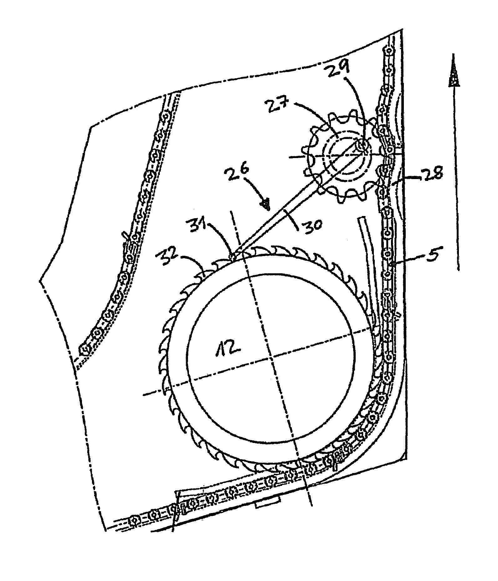
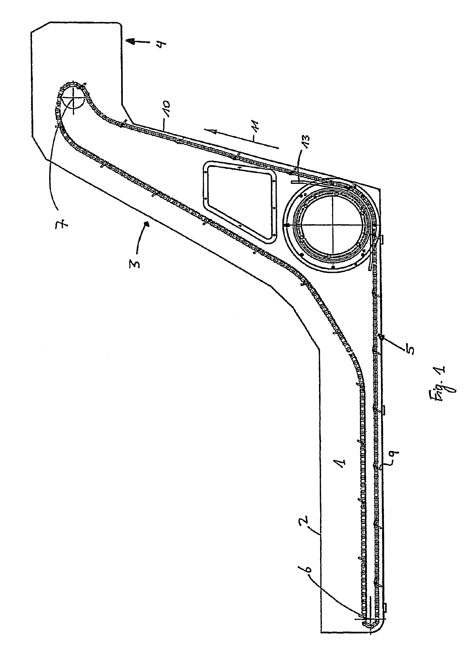
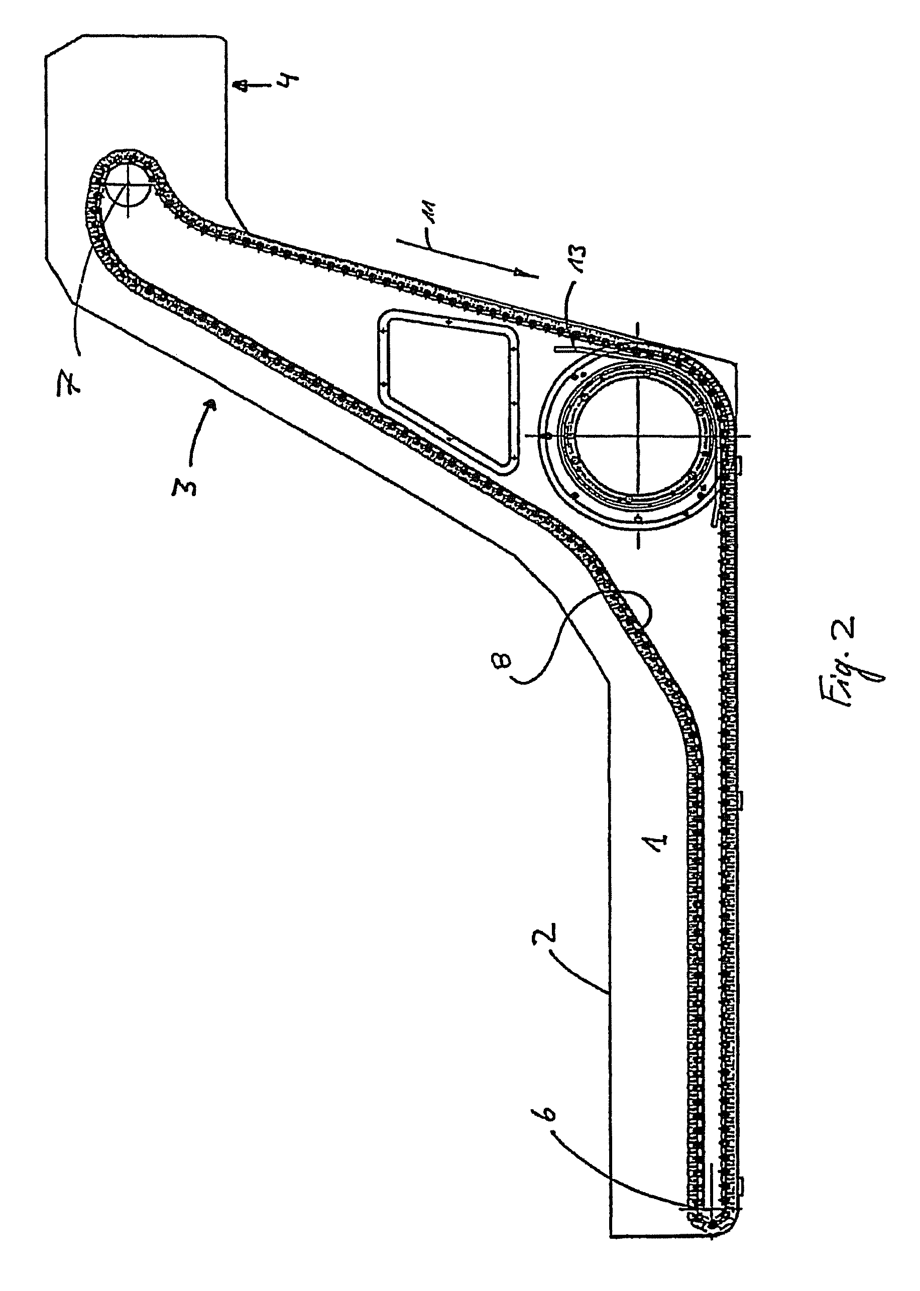
[0021]FIG. 1 shows the side view of an embodiment of the device according to the invention having a receiving tank 1 which is open at the top and which receives chips and cooling liquid collecting on machine tools. This receiving tank has an overflow edge 2. Adjoining the receiving tank is a rising guide section 3, which merges into an elevated delivery section 4.

[0022]Here, a scraper chain roller-guided on both sides is provided as transport element. This scraper chain is guided around a bottom deflecting element 6 at the end of the receiving tank 1 and runs in the region of the delivery section 4 around a top deflecting element 7, which is coupled to a drive (not shown). It carries scraper elements which are arranged at a distance apart and which project downwards in the region of the bottom strand, that is to say in the direction of the bottom of the receiving tank 1, or towards the side wall 10 of the rising section 3. The transport direction of the scraper chain 1 is indicated ...


PUM

PropertyMeasurementUnit
crank radiusaaaaaaaaaa
radial distanceaaaaaaaaaa
circumferential speedaaaaaaaaaa

Abstract

A device for receiving and separating chips and cooling liquid collecting on machine tools. The device may include a transport element that is guided along a filter drum at a radial distance from the latter on guide rails, and cooperating driver elements acting only in the circumferential direction on the filter drum and arranged in each case at a distance from one another are provided on the transport element and on the filter drum.

Description

RELATED APPLICATIONS[0001]This is a continuation of U.S. patent application Ser. No. 10 / 492,285 filed Apr. 9, 2004, for DEVICE FOR RECEIVING AND SEPARATING CHIPS AND COOLING LIQUID (DRIVE) COLLECTING ON MACHINE TOOLS MODULAR FLUID SPRAY GUN, set to issue on Oct. 3, 2006 as U.S. Pat. No. 7,115,200, the entire disclosure of which is fully incorporated herein by reference.BACKGROUND AND SUMMARY[0002]The invention relates to a device for receiving and separating chips and cooling liquid collecting on machine tools, the cooling liquid being returned for reuse and the chips being discharged, having a receiving tank for receiving the chips and the cooling liquid, a rising guide section adjoining the receiving tank, an elevated delivery section adjoining the guide section, a chain-like closed transport element which, at least in the region receiving the chips and the cooling liquid and in the delivery section, is guided via deflecting elements, of which at least one is coupled to a rotary d...

Claims


Application Information

Patent Timeline
Patent Type & Authority Patents(United States)
IPC IPC(8): B23Q11/00B01D33/06B01D33/073B01D36/04B23Q11/10
CPCB01D33/073B23Q11/0057B23Q11/1069B01D33/466B01D33/76B01D33/801B01D2201/089Y02P70/10B23Q11/00
Inventor ACKERMANNS, LEO J. P.ARNTS, WIM R. E.SIEBEN, RENE MSOUREN, RIMMOND H. B.
Owner MAYFRAN INT BV
Why Eureka
Try Eureka